علم وهندسة تثبيت الهوائيات المثالية: دليل فني
النصيحة النموذجية لتركيب الهوائي بسيطة: "ركبه بأعلى ما يمكن." على الرغم من أن هذا ليس خطأ، إلا أن هذه القاعدة البسيطة تلمس فقط سطح مجال تقني معقد. تحسين الأداء الحقيقي والسلامة على المدى الطويل لا يأتي من الارتفاع فقط، بل من تطبيق المبادئ العلمية بعناية. الحصول على التركيب المثالي يتطلب فهم كيفية عمل فيزياء الإشارة، والهندسة الإنشائية، والتوافق الكهرومغناطيسي، والسلامة الكهربائية جميعها معًا. هذا الدليل يتجاوز النصائح الأساسية ليقدم لك المعلومات التقنية أساس لاتخاذ قرارات ذكية.
يقدم هذا المقال استكشافًا كاملًا لتركيب الهوائيات المهنية، ويشمل:
- إن الفيزياء الأساسية التي تتحكم في كيفية انتقال الإشارات وتفاعلها مع البيئة.
- الآليات الهيكلية اللازمة لبناء تركيب آمن وطويل الأمد يمكنه تحمل القوى البيئية.
- مبادئ التوافق الكهرومغناطيسي لمنع التركيب نفسه من تقليل جودة الإشارة.
- المتطلبات الأساسية للأرضي الكهربائية لضمان السلامة وحماية المعدات.
ما هو تركيب الهوائي الفني؟
من وجهة نظر تقنية، تركيب الهوائي ليس مجرد مهمة مادية لتثبيت الأجهزة. إنه أمر حاسم عملية الهندسة الذي يحدد جزءًا كبيرًا من الأداء العام والسلامة لنظام التردد الراديوي (RF). يتضمن دمج مجالات دراسية متعددة لوضع الهوائي في أفضل موقع واتجاه، مع التأكد من قدرته على تحمل الضغوط البيئية طوال مدة خدمته. المفاهيم الأساسية التي سنستكشفها هي:
- فيزياء الترددات الراديوية (RF): كيف يؤثر الارتفاع المحدد والموقع والاتجاه للهوائي مباشرة على قوة الإشارة وجودتها وقدرتها على تجاوز العقبات لكل من الاستقبال والإرسال.
- الهندسة الإنشائية: كيفية حساب ومواجهة القوى، خاصة حمولة الرياح، لضمان أن يكون التركيب آمنًا ومستقرًا ولا يشكل خطرًا على الممتلكات أو الأشخاص.
- الكهرومغناطيسية & علم الموادكيف يمكن لمعدات التركيب، والعمود، والأجسام المعدنية القريبة أن تتفاعل مع المجال الكهرومغناطيسي للهوائي، مما قد يغير أدائه، وكيف يؤثر اختيار المادة على العمر الافتراضي.
—
فيزياء انتشار الإشارة
لتحسين موضع الهوائي، يجب أن نفهم أولاً الفيزياء التي تحدد كيفية انتقال الموجات الراديوية من المرسل إلى المستقبل. تساعد هذه المعرفة المُثبت على تشخيص مشاكل الإشارة واتخاذ القرارات بناءً على المبادئ العلمية بدلاً من التخمين.
خط الرؤية وما بعده
مفهوم خط الرؤية (LOS) أساسي للعديد من أنظمة الترددات الراديوية، خاصة عند الترددات الأعلى مثل تلفزيون UHF، وشبكات الجيل الخامس (5G)، والواي فاي. ومع ذلك، فإن خط الرؤية RF أكثر تعقيدًا من مسار بصري بسيط.
- الرؤية المباشرة البصرية مقابل خط الراديو المباشر: مسار بصري واضح هو نقطة انطلاق جيدة، لكنه لا يضمن مسار راديو واضح. تتأثر الموجات الراديوية بأكثر من مجرد الأجسام الصلبة. يمكن للغلاف الجوي نفسه أن ينحني الموجات الراديوية، مما يسمح لها بالانتقال قليلاً وراء الأفق البصري. يُعرف هذا الظاهرة باسم الأفق الراديوي، وهو تقريبًا يساوي 4/3 من الأفق الهندسي.
- تأثير الارتفاع: زيادة ارتفاع الهوائي توفر فائدتين رئيسيتين. أولاً، ترفع الهوائي مباشرة فوق العوائق القريبة على مستوى الأرض. ثانيًا، تمد مدى الإشارة بسبب انحناء الأرض. يمكن للهوائي الأعلى أن "يرى" برج الإرسال الذي سيكون مخفيًا تحت الأفق بخلاف ذلك.
- العوائق: الأجسام في مسار الإشارة يمكن أن تمتص أو تعكس أو تشتت طاقة التردد اللاسلكي.
- الامتصاص: المواد الكثيفة غير المعدنية هي المسبب الرئيسي لامتصاص الإشارة. الأوراق (خصوصًا عندما تكون مبللة)، الجدران الخرسانية السميكة، والهياكل الطوبية تمتص كميات كبيرة من طاقة التردد اللاسلكي، وتحولها إلى حرارة وتضعف الإشارة.
- الانعكاس والمتعدد المسارات: تتناثر الموجات الراديوية على الأسطح الكبيرة والمسطحة مثل المباني وأبراج المياه أو التلال. عندما تصل هذه الإشارات المنعكسة إلى الهوائي المستقبل وهي خارج الطور مع الإشارة المباشرة، يمكن أن تتسبب في إلغاء جزئي أو كلي للإشارة. يُعرف هذا التأثير باسم تلاشي متعدد المسارات، وهو سبب شائع لانقطاع الإشارة وظهور الظلال الرقمية. يمكن أن يساعد التمركز الاستراتيجي، حتى بتحريك الهوائي بعدة أقدام، في العثور على نقطة مثالية تقلل من التداخل المدمر متعدد المسارات.
المنطقة الحاسمة فريزل
وجود خط رؤية واضح ومباشر فقط غير كافٍ لتحقيق الأداء الأمثل. يجب أن يكون المجال المحيط مباشرةً بالمسار المباشر أيضًا خاليًا إلى حد كبير من العوائق. يُعرف هذا المنطقة باسم منطقة فريسنل.
- ما هي المنطقة فريزلن؟ تخيل منطقة بيضاوية على شكل سيجار تمتد بين الهوائيات المرسلة والمستقبلة. هذه هي المنطقة فريزلن الأولى. جزء كبير من طاقة الإشارة يسافر داخل هذه المنطقة، وليس فقط على طول الخط المركزي المباشر.
- لماذا يهم الأمر: العوائق التي لا تعيق خط الرؤية المباشر ولكنها تبرز في منطقة فريزل يمكن أن تتسبب لا زال في تدهور كبير في الإشارة. حيث يتعرض الإشارة للانحراف حول حافة الجسم، وتحدث لها تغير في الطور. ثم يتداخل الإشارة المنحرفة مع الإشارة المباشرة عند المستقبل، مما يقلل من قوة الإشارة الإجمالية. قاعدة شائعة هي أن المنطقة الأولى لفريزل يجب أن تكون على الأقل 60% خالية من العوائق لتقليل فقدان الإشارة إلى الحد الأدنى.
- التطبيق العمليعلى الرغم من أن الحسابات الدقيقة قد تكون معقدة، إلا أن صيغة مبسطة تساعد في تقدير نصف قطر منطقة فريزل عند أوسع نقطة لها (في منتصف المسافة بين الهوائيات). للمسوح الميدانية العملية، فهم هذا المفهوم أكثر أهمية من الحساب الدقيق. على سبيل المثال، قد يكون لدى هوائي على السطح يوجه نحو برج على بعد بضعة أميال خط رؤية واضح، ولكن إذا مر مسار الإشارة فوق سطح مبنى قريب أو خط أشجار كثيف، فإن منطقة فريزل تكون معيقة، وسيؤثر ذلك على الأداء. رفع الهوائي بضع أقدام إضافية لتجاوز هذا العائق يمكن أن يؤدي إلى تحسين كبير.
استقطاب الهوائي واتجاهه
يشير الاستقطاب إلى اتجاه المجال الكهربائي للموجة الراديوية. لنقل الإشارة بأقصى قدر ممكن، يجب أن تتشارك الهوائي المستقبل نفس استقطاب الهوائي المرسل.
- الاستقطاب العمودي مقابل الأفقي: في الاستقطاب الأفقي، يكون المجال الكهربائي موازياً لسطح الأرض. هذا هو المعيار لمعظم بث الراديو FM والتلفزيون الرقمي. في الاستقطاب العمودي، يكون المجال الكهربائي عمودياً على سطح الأرض، وهو شائع للهاتف المحمول الاتصالات وراديو الهاتف المحمول للأرض.
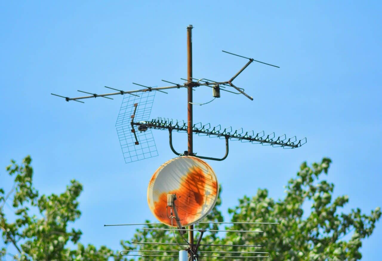
- تركيب لضبط الاستقطاب الصحيح: يجب أن يسمح معدات التركيب بتثبيت الهوائي في الاتجاه الصحيح. بالنسبة لهوائي التلفزيون ياجي-ودا النموذجي، يعني ذلك أن العناصر (القضبان العرضية) يجب أن تكون أفقية تمامًا. إذا انحنى أو التوى التركيب مع مرور الوقت، مما يغير الاستقطاب، ستنخفض قوة الإشارة بشكل كبير.
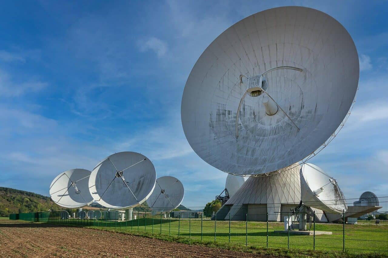
- الاستقطاب الدائري: يُستخدم في اتصالات الأقمار الصناعية (مثل نظام تحديد المواقع العالمي، راديو الأقمار الصناعية) وبعض التطبيقات المتخصصة الأخرى، ويتضمن الاستقطاب الدائري دوران المجال الكهربائي أثناء انتشاره. ميزة رئيسية له هي أنه أقل حساسية لاتجاه الهوائي، مما يجعله أكثر متانة للروابط المتنقلة والأقمار الصناعية حيث قد يتغير اتجاه المستقبل.
—
تصميم قاعدة آمنة ومستقرة
تركيب الهوائي هو هيكل يجب تصميمه لتحمل قوى مادية كبيرة. عدم احترام هذه القوى يمكن أن يؤدي إلى تلف الممتلكات، فقدان المعدات، ومخاطر سلامة خطيرة.
فهم حمولة الرياح
أهم قوة تؤثر على تركيب الهوائي هي الريح. هذه القوة ديناميكية ومتغيرة، ويمكن أن تكون هائلة أثناء العاصفة.
- الحمولة الثابتة مقابل الحمولة الديناميكية: الحمولة الثابتة هي القوة الثابتة والمنخفضة لوزن الهوائي والعمود. وهي صغيرة نسبياً وسهلة الإدارة. الحمولة الديناميكية هي القوة التي يفرضها الريح، والتي تكون أكبر بكثير وتعمل أفقياً.
- العوامل المؤثرة على حمولة الرياح:
- مساحة سطح الهوائي وشكله: العامل الأكثر أهمية هو مساحة سطح الهوائي المعرضة للريح. الهوائي الكبير الصلب سيكون معرضًا لقوى أكبر بكثير من هوائي ياجي الشبكي أو الهيكلي بنفس الأبعاد.
- ارتفاع العمود وذراع العزم: العمود الطويل يعمل كرافعة، أو ذراع عزم. هذا يضاعف بشكل كبير قوة الريح على الهوائي وينقلها إلى حوامل التثبيت والهيكل. على سبيل المثال، مضاعفة ارتفاع العمود تقريبًا يضاعف العزم وبالتالي الإجهاد على قاعدة التركيب.
- سرعة الرياح: القوة التي يفرضها الريح ليست خطية؛ فهي تزداد بمربع سرعة الريح. هذا يعني أن هبة ريح من 50 ميل في الساعة إلى 100 ميل في الساعة لا تضاعف القوة فقط — بل تربعها.
- معايير الصناعة: للتركيبات الحرجة والتجارية، يشير المهندسون إلى معايير مثل TIA-222 (حالياً في إصدارها 'H'). توفر هذه المعايير منهجيات مفصلة لحساب أحمال الريح والجليد على هياكل دعم الهوائي، لضمان تصميمها مع عوامل أمان مناسبة.
الجدول 1: تقدير مبسط لحمولة الرياح
لتوضيح القوى القوية السارية، يوفر الجدول التالي تقديرًا مبسطًا للقوة الأفقية على الهوائي. هذا لأغراض تعليمية فقط ويجب ألا يحل محل تحليل هيكلي محترف للتركيبات الكبيرة أو الحرجة.
| مساحة سطح الهوائي | سرعة الرياح (ميل في الساعة) | القوة المقدرة على القاعدة (رطل) |
| 2 قدم مربع | 60 ميل في الساعة | ~18 رطل |
| 2 قدم مربع | 90 ميل في الساعة | ~41 رطل |
| 5 قدم مربع | 60 ميل في الساعة | ~46 رطل |
| 5 قدم مربع | 90 ميل في الساعة | ~103 رطل |
*تنويه: القوة محسوبة باستخدام الصيغة F = A × P × Cd، حيث P = 0.00256 × V²، مع افتراض معامل مقاومة السحب (Cd) يساوي 1.2 للوحة مسطحة. ستختلف القوى الفعلية بناءً على شكل الهوائي، والتجمد، وعوامل الرياح المفاجئة.*
اختيار معدات التركيب الخاصة بك
إن اختيار معدات التركيب هو قرار في المادة العلم. المادة المناسبة تضمن أن يكون التركيب قويًا بما يكفي وسيقاوم التدهور البيئي على مدى عمره.
- الخصائص التي تهم:
- قوة الشد: قدرة المادة على مقاومة التمزق. الفولاذ يوفر قوة شد عالية جدًا، مما يجعله مثاليًا للتطبيقات ذات الإجهاد العالي.
- مقاومة التآكل: القدرة على مقاومة الصدأ (للصلب) أو الأكسدة (للألمنيوم). هذا أمر أساسي لطول العمر، خاصة في المناطق الرطبة، الساحلية، أو الصناعية التي تحتوي على ملوثات جوية.
- التآكل الكهروكيميائي: هو ظاهرة حاسمة وغالبًا ما يتم تجاهلها. عندما يكون معدنان مختلفان على اتصال كهربائي في وجود إلكتروليت (مثل مياه الأمطار)، يشكلان بطارية صغيرة. المعدن الأكثر نشاطًا سيتآكل بمعدل متسارع. مثال شائع هو استخدام معدات فولاذية (مثل البراغي U) لتثبيت هوائي الألمنيوم على عمود. الفولاذ سيسرع تآكل الألمنيوم عند نقطة الاتصال، مما يؤدي في النهاية إلى الفشل.
الجدول 2: تحليل مواد التركيب
يوفر هذا الجدول تحليلًا مقارنًا للمواد الشائعة المستخدمة للأعمدة، والأقواس، والملحقات، لمساعدتك على اتخاذ قرار مستنير بناءً على بيئتك واحتياجاتك الخاصة.
| المواد | قوة التحمل إلى الوزن | مقاومة التآكل | خطر التآكل الكهروكيميائي | التكلفة | أفضل حالة استخدام |
| الفولاذ المجلفن | عالية | جيد (يعتمد على الطلاء) | متوسط (مع الألمنيوم) | منخفضة | للأغراض العامة، احتياجات عالية من القوة |
| ألمنيوم | ممتاز | جيد جداً | منخفض (عند استخدامه مع نفسه) | متوسط | صواريخ خفيفة الوزن، مناطق منخفضة الرياح |
| الفولاذ المقاوم للصدأ | عالية جداً | ممتاز | منخفض (ولكن يمكن أن يختلف حسب الدرجة) | عالية | بيئات ساحلية / تآكلية، على المدى الطويل |
| صلب مطلي بالمسحوق | عالية | يختلف (سيء إذا خدش) | عالي (إذا تم كسر الطلاء) | منخفضة-متوسطة | مركز على الجمالية، مناخات غير قاسية |
—
أفضل ممارسات التوافق الكهرومغناطيسي والتركيب
يشير التوافق الكهرومغناطيسي (EMC) في هذا السياق إلى ضمان عدم تدخل نظام التركيب وبيئته المباشرة في وظيفة الهوائي. الحامل ليس مجرد دعم سلبي؛ إنه جزء من البيئة الكهرومغناطيسية للهوائي.
الحامل كجزء من النظام
يمكن أن يصبح الصاري المعدني أو الحامل، تحت ظروف معينة، جزءًا غير مقصود من الهوائي نفسه، مما يغير أدائه.
- الحوامل الموصلة مقابل غير الموصلة: يمكن أن يعمل الحامل المعدني في المجال القريب للهوائي كعنصر طفيلي. اعتمادًا على حجمه وقربه، يمكن أن يعكس أو يعيد إشعاع طاقة RF، ويتفاعل مع نمط الإشعاع المقصود للهوائي.
- تأثير إلغاء التردد: عندما يتم وضع جسم معدني كبير جدًا بالقرب من عناصر الهوائي النشطة، يمكن أن يتصل بالمجال الكهرومغناطيسي للهوائي. يمكن لهذا الاتصال أن يحول تردد الرنين للهوائي ويغير مقاومته. النتيجة هي تطابق مقاومة ضعيف مع الكابل المحوري، مما يؤدي إلى نسبة الموجة الواقفة (SWR) عالية وخسارة كبيرة في نقل الإشارة.
- قاعدة عامة للمسافة بين الهوائي والأشياء الأخرى: لتقليل هذه التفاعلات غير المرغوب فيها، حافظ على أكبر قدر ممكن من المسافة بين عناصر الهوائي النشطة وأي أسطح معدنية متوازية كبيرة (مثل مدخنة معدنية، أو صاري آخر، أو جدران معدنية). الإرشاد العام هو الحفاظ على مسافة تفصل نصف طول الموجة على الأقل عند أدنى تردد للعمل. بالنسبة لنطاق تلفزيون UHF، يعادل ذلك مسافة فصل حوالي 1-2 قدم.
الكوابل والاتصالات
الكابل المحوري وموصلاته هو الرابط النهائي في السلسلة. الاختيارات السيئة أو التركيب غير الدقيق هنا يمكن أن يلغي كل جهود وضع الهوائي بشكل مثالي.
- جودة الكابل المحوري: الإشارة التي تنتقل من الهوائي إلى المستقبل ضعيفة وعرضة للفقد. استخدام كابل محوري عالي الجودة ومنخفض الفاقد هو استثمار حاسم. للبث التلفزيوني والاستقبال العام، يُعد RG6 Quad-Shield معيارًا شائعًا. للمدى الطويل أو الترددات الأعلى (مثل راديو HAM)، توفر كابلات مثل LMR-400 فقدان إشارة أقل بشكل كبير لكل قدم.
- حلقة التنقيط: هذه تفصيل بسيط ولكنه حيوي. قبل دخول الكابل إلى المنزل أو توصيله بلوحة التأريض، يجب أن يُلف لأسفل أسفل مستوى نقطة الدخول. هذا يُنشئ
- عزل الموصلات ضد العوامل الجوية: الاتصال بين الهوائي والكابل المحوري هو النقطة الأكثر عرضة للخطر في النظام الخارجي بأكمله. دخول الرطوبة سيؤدي إلى تآكل الاتصال، وتدهور الإشارة، وفي النهاية قد يؤدي إلى فشل كامل. يجب أن يكون هذا الاتصال مقاوم للعوامل الجوية باستخدام مادة مانعة للتسرب للكابل المحوري، وشحم السيليكون العازل داخل الموصل، و/أو غلاف من شريط مطاطي ذاتي الالتصاق (ذاتية الالتئام).
- توجيه الكابل: قم بتثبيت الكابل المحوري على الصاري والهياكل باستخدام روابط أو مشابك مقاومة للأشعة فوق البنفسجية. تجنب الانحناءات الحادة، التي يمكن أن تغير مقاومة الكابل وتتسبب في انعكاسات إشارة. أيضًا، تجنب شد الروابط بقوة لدرجة تشويه عازل الكابل، مما قد يضعف الأداء أيضًا.
التأريض، والتوصيل، والسلامة
تأريض تركيب هوائي خارجي بشكل صحيح ليس خطوة اختيارية؛ إنه متطلب سلامة غير قابل للتفاوض. يحمي المنزل والمعدات الإلكترونية والسكان من مخاطر الصواعق والتفريغ الساكن. يجب أن يتوافق جميع أعمال التأريض مع القوانين الكهربائية المحلية، مثل الكود الكهربائي الوطني (NEC) في مصر.
لماذا التأريض غير اختياري
غالبًا ما يُساء فهم هدف نظام تأريض الهوائي. وظيفته مزدوجة: حماية من الصواعق وتفريغ الساكن.
- حماية من الصواعق: نظام التأريض لا يمنع حدوث صاعقة برق. لا شيء يمكنه ذلك. بدلاً من ذلك، هدفه هو توفير مسار مخصص ومنخفض المقاومة للتيار الكهربائي الهائل الناتج عن الصاعقة ليتمكن من السفر بأمان إلى الأرض. بدون هذا المسار، قد يختار التيار السفر عبر الأسلاك الكهربائية المنزلية، والسباكة، والأجزاء الهيكلية، مما قد يسبب حريقًا، انفجارات، وأضرار كارثية.
- تراكم الساكنة: الرياح والأمطار التي تتحرك عبر الهوائي يمكن أن تولد شحنة كهربائية ساكنة كبيرة. إذا لم يتم تصريف هذه الشحنة بأمان إلى الأرض، يمكن أن تتراكم وتفرغ عبر الكابل المحوري إلى مكبر الصوت الأمامي الحساس في التلفزيون أو الراديو، مما يسبب تلفًا دائمًا. يوفر التأريض الصحيح مسارًا ثابتًا لتفريغ هذه الشحنة بشكل آمن.
مكونات التأريض الأساسية
نظام التأريض الكامل، كما هو موضح في معايير مثل المادة 810 من الكود الكهربائي الوطني، يتكون من مسار مستمر من الهوائي إلى الأرض.
- تأريض عمود الهوائي: يجب توصيل العمود المعدني مباشرةً إلى موصل التأريض باستخدام مشبك تأريض مناسب.
- وحدة تفريغ الهوائي: قبل دخول الكابل المحوري إلى المنزل، يجب أن يتوقف بواسطة وحدة تفريغ الهوائي أو وحدة التأريض. تسمح هذه الوحدة بمرور إشارة الكابل مع توصيل الدرع الخارجي للكابل إلى نظام التأريض.
- سلك التأريض: يُستخدم سلك نحاسي أو ألومنيوم بقطر ثقيل كالموصل الرئيسي للتأريض. يجب أن يمتد في مسار مستقيم وقصير قدر الإمكان من العمود ووحدة التأريض إلى نقطة الاتصال بالأرض.
- عمود التأريض والتوصيل: يتصل موصل التأريض بواحد أو أكثر من أعمدة التأريض المخصصة (عادةً أعمدة بطول 8 أقدام تُدفع في الأرض). والأهم من ذلك، يجب توصيل نظام تأريض الهوائي الجديد هذا إلى أرض خدمة الكهرباء الرئيسية للمنزل باستخدام موصل توصيل بقطر ثقيل. يضمن ذلك أن تكون جميع نقاط التأريض عند نفس الجهد الكهربائي، مما يمنع حدوث فروق جهد خطيرة أثناء حدوث الصاعقة.
الجدول 3: مواصفات التأريض
يحدد هذا الجدول الحد الأدنى لمواصفات المكونات استنادًا إلى مبادئ من الكود الكهربائي الوطني. هذه لأغراض إعلامية فقط. دائمًا استشر واتباع قوانين الكهرباء المحلية ويفضل توظيف كهربائي مؤهل لهذا العمل الحساس بالسلامة.
| المكون | مواصفة مستندة إلى NEC | الأساس المنطقي |
| سلك التأريض | حد أدنى 10 AWG نحاس أو 8 AWG ألومنيوم. | يجب أن يكون قادرًا على تحمل التيار الهائل الناتج عن الصاعقة دون أن يتبخر. |
| موصل التوصيل | حد أدنى 6 AWG نحاس. | يضمن اتصال منخفض المقاومة بين قضيب أرضية الهوائي والأرضية الرئيسية للمنزل. |
| قضيب الأرض | عادةً طوله 8 أقدام، وقطره 5/8 بوصة من الصلب المغلف بالنحاس. | يجب أن يُدفع بعمق كافٍ للوصول إلى التربة الرطبة للتبديد الفعال. |
| مشابك | يجب أن تكون مصنفة للدفن المباشر والاستخدام الخارجي. | يضمن اتصالًا متينًا ومنخفض المقاومة لن يتآكل أو يفشل. |
—
الخلاصة: تركيب المبادئ بشكل متكامل
تركيب الهوائي المثالي ليس نتيجة إجراء واحد بل هو تتويج لاستراتيجية متماسكة. يبدأ بفهم فيزياء الترددات الراديوية لتوجيه اختيار الموقع وينتهي بتنفيذ دقيق لأفضل الممارسات الهيكلية والكهربائية. من خلال تجاوز الاعتبارات البسيطة للارتفاع، يمكننا إنشاء تركيب يوفر أقصى أداء للإشارة، وسلامة لا تقبل المساومة، ومتانة طويلة الأمد.
ملخص المبادئ الأساسية
- الأداء يتحدد بواسطة الفيزياء. الموقع الأمثل يُحدد من خلال تحليل خط الرؤية، وضمان خلو منطقة فريسل، وتقليل تداخل المسارات المتعددة، مع احترام استقطاب البث.
- السلامة تضمنها الهندسة. يجب التعامل مع التركيب كهيكل، مع اختيار الحوامل والأجهزة لتلبية حمل الرياح المحسوب ومنع الفشل الميكانيكي.
- الدوام يأتي من الاهتمام بالتفاصيل. تعتمد موثوقية النظام على التطبيق الصحيح لعلوم المواد، والتدقيق في مقاومة الطقس لجميع الاتصالات، ونظام تأريض مطابق للرموز.
قائمة التحقق الفنية النهائية
قبل بدء أي تركيب، قم بمراجعة هذه القائمة النهائية لضمان النظر في جميع الجوانب الفنية.
- مسح الموقع: هل قمت بتحليل خط الرؤية الواضح، وخلو منطقة فريسل الكافية، ومصادر الانعكاس المتعددة المحتملة؟
- الخطة الهيكلية: هل أخذت في الاعتبار مساحة سطح الهوائي، وارتفاع العمود، وظروف الرياح المحلية لاختيار حاملة وأجهزة مناسبة للمهمة؟
- توافق المواد: هل المواد المختارة للعمود، والحامل، والمثبتات مناسبة لمناخك ومتوافقة كيميائيًا لمنع التآكل؟
- السلامة أولاً: هل لديك خطة كاملة ومتوافقة مع الرموز لتأريض العمود وربط النظام بأرضية الكهرباء الرئيسية للمنزل قبل أن تبدأ؟
- خطة التنفيذ: هل ستستخدم حلقة تنقيط لكيبل الكوكسال، وتقوم بعزل جميع الاتصالات الخارجية بشكل كامل ضد العوامل الجوية، وتؤمن جميع الكابلات بشكل صحيح لمنع التلف؟
- نظرية وتصميم الهوائيات – نظرية الهوائيات https://www.antenna-theory.com/
- معايير هندسة الترددات اللاسلكية – IEEE https://www.ieee.org/
- الهوائي (الراديو) – ويكيبيديا https://en.wikipedia.org/wiki/Antenna_(radio)
- معايير الاتصالات السلكية واللاسلكية – ITU https://www.itu.int/
- معايير تركيب الهوائيات – TIA (جمعية صناعة الاتصالات) https://www.tiaonline.org/
- هندسة الترددات الراديوية والأمواج الدقيقة – ScienceDirect https://www.sciencedirect.com/topics/engineering/antenna-installation
- معايير السلامة الكهربائية – NFPA (الجمعية الوطنية للحماية من الحرائق) https://www.nfpa.org/
- المعايير الهيكلية لأبراج الهوائيات – TIA-222 https://www.tiaonline.org/resources/standards/
- هندسة الترددات الراديوية – ARRL (الرابطة الأمريكية لإعادة الإرسال الإذاعي) https://www.arrl.org/
- تعليم هندسة الاتصالات – MIT OpenCourseWare https://ocw.mit.edu/


