بناء مسارات السكك الحديدية: دليل كامل لبناء المسارات الحديثة
مقدمة
يشرح هذا المقال الأفكار الرئيسية وراء بناء مسارات السكك الحديدية اليوم. بدلاً من مجرد وصف ما يحدث على السطح، سننظر عن كثب في الهندسة، العلم، والمواد التي تجعل من بناء السكك الحديدية يعمل. هذا الدليل ذو قيمة لأنه يتعمق في الموضوع، موضحًا كيف تعمل الأجزاء المختلفة والأساليب المعقدة معًا لإنشاء نظام نقل آمن وفعال. سنبدأ بتفكيك الأجزاء الأساسية لبنية المسار. ثم نستكشف القواعد العلمية التي تتحكم في حركة القطارات، نقارن بين طرق بناء المسارات، ونختتم بالنظر إلى التكنولوجيا المتقدمة وفحوصات الجودة التي تحدد مشاريع اليوم. طوال الوقت، نركز على الجمع بين الهندسة الدقيقة، العمليات الفعالة، والسلامة الكاملة.
أجزاء المسار
مسار السكك الحديدية ليس هيكلًا بسيطًا؛ إنه نظام معقد من الأجزاء المهندسة، كل منها له وظيفة محددة مصممة لتحمل القوى الهائلة والضغوط البيئية. فهم هذه الأجزاء هو الخطوة الأولى نحو فهم عملية البناء بأكملها. يقسم هذا القسم كل مكون، مجيبًا على سؤال “ما هو” قبل أن نغوص في “كيف”.
المكونات الرئيسية وما تقوم به
- السكك الحديدية:
- ما تقوم به: الوظيفة الرئيسية للسكك هي توجيه عجلات القطار، وتوفير سطح ناعم ومتواصل ومنخفض الاحتكاك للتشغيل، والتعامل مع القوى الهائلة الناتجة عن حركة المرور. فهي الرابط المباشر بين المركبة والبنية التحتية.
- علم المواد: تصنع السكك من الصلب عالي الكربون، مع درجات مثل R260 و R350HT شائعة. غالبًا ما تتضمن عملية التصنيع تصلب الرأس، حيث يتم تبريد رأس السكة بسرعة لخلق بنية دقيقة. هذا يزيد بشكل كبير من صلابتها، مما يجعلها أكثر مقاومة للتآكل وبداية تعب الاتصال الدوّار، وهو آلية فشل حاسمة.
- الأوتاد (الرباطات):
- ما تقوم به: الأوتاد هي الأعضاء العرضية التي تنقل الأحمال المتحركة من السكك إلى الحصى. وظائفها الحرجة الأخرى هي الحفاظ على عرض المسار الصحيح وتوفير قاعدة مستقرة لتأمين نظام التثبيت.
- الأنواع والتحليل: الأوتاد المصنوعة من الخرسانة مسبقة الإجهاد هي المعيار للخطوط الرئيسية عالية السرعة والكثافة المرورية لأنها تدوم لفترة طويلة، وتزن، وتوزع الحمل بشكل متسق. الأوتاد الخشبية الصلبة توفر مرونة أكبر وأسهل في التعامل، مما يجعلها مناسبة للمفاتيح والمناطق ذات الظروف الأرضية الأقل استقرارًا، على الرغم من أنها يمكن أن تتدهور مع مرور الوقت. الأوتاد الفولاذية خفيفة الوزن ومتينة، لكنها قد تطرح تحديات مع عزل دائرة المسار.
- أنظمة التثبيت:
- ما تقوم به: نظام التثبيت هو الرابط الحاسم الذي يثبت السكة على الأوتاد. يجب أن يقاوم القوى الرأسية والجانبية والطولية القوية لمنع حركة السكة. وظيفة ثانوية رئيسية هي توفير العزل الكهربائي، وهو ضروري لأنظمة الإشارة الحديثة وكشف القطارات.
- التحليل الفني: تستخدم السكك الحديدية الحديثة بشكل رئيسي أنظمة تثبيت مرنة، مثل مشبك باندرول e-Clip أو أنظمة فوسشو. توفر هذه المشابك المصنوعة من الصلب المرن قوة تثبيت ثابتة تمسك السكة بشكل آمن مع السماح بحركة عمودية طفيفة، مما يساعد على امتصاص الاهتزازات. هذا تحسن كبير على أنظمة التثبيت الصلبة القديمة، التي كانت عرضة للارتخاء تحت الأحمال المتحركة.
- الركام والأساس الفرعي:
- ما تقوم به: الركام هو طبقة من الحصى المكسرة تدعم الأوتاد. الوظائف الأساسية لها هي توفير تصريف فعال، توزيع الحمل من الأوتاد على الأرض أدناه، منع نمو النباتات، والأهم من ذلك، السماح بالتعديلات الدقيقة على هندسة المسار من خلال عملية تسمى التمطيط.
- مبادئ هندسة الأرض: يتكون الركام المثالي من حجارة مكسرة ذات زوايا وصلابة، مثل الجرانيت أو البازلت. الشكل الزاوي يسمح للحجارة بالتشابك، مما يوفر مقاومة قوية للحركة. تحت الركام يوجد الأساس الفرعي، وهو طبقة من مادة ذات درجة أصغر تعمل كمفصل، تمنع الحجارة الأكبر من الدفع إلى الأرض الأضعف أدناه.
تفاصيل المكونات
يلخص الجدول التالي التفاصيل الفنية الرئيسية ووظائف مكونات المسار الأساسية، موفرًا مرجعًا سريعًا للمهندسين والفنيين.
| المكون | المواد الشائعة | الوظيفة الهندسية الأساسية(الأساسية) | أنماط الفشل الحرجة |
| السكة الحديدية | الفولاذ عالي الكربون (مثل UIC 60، AREMA 136) | – توفير سطح تشغيل سلس ومنخفض الاحتكاك<br>- توجيه شفات العجلات<br>- تحمل ضغوط التلامس وقوى الانحناء | – تعب الحمل الدوراني<br>- التجعيد<br>- تآكل الرأس |
| الالتر (الربط) | الخرسانة مسبقة الإجهاد، الخشب الصلب، الصلب، المركب | – الحفاظ على عرض المسار<br>- نقل وتوزيع الأحمال على الحصى<br>- نظام تثبيت آمن | تشقق الخرسانة<br>تآكل الخشب<br>ربط المركز |
| نظام التثبيت | الصلب الربيعي، الحديد المطاوع القابل للطرق، عوازل النايلون | تأمين السكة على السرير<br>توفير المرونة وامتصاص الاهتزازات<br>ضمان العزل الكهربائي للإشارات | – فقدان حمولة إصبع القدم<br>- فشل العازل<br>- تدهور الوسادة |
| الكتل الرملية | الصخور الصلبة المكسرة والزوايا (مثل الجرانيت، البازلت) | توفير التصريف<br>توزيع الحمولة على الطبقة التحتية<br>مقاومة حركة السكة الجانبية والطولية | التلوث (الملوثات)<br>تدهور الجسيمات<br>تصريف سيء |
علم الحركة
مع تحديد المكونات الثابتة، ننتقل الآن إلى المبادئ النشطة لهندسة المسار. هذه هي القواعد الأساسية للفيزياء والهندسة التي تتحكم في كيفية حركة القطار بأمان وراحة وكفاءة على طول المسار. الهندسة الصحيحة ليست خيارًا؛ إنها متطلب لسكك حديدية وظيفية.
الاستقرار والراحة
- عرض المسار:
- المبدأ: العرض هو المسافة الدقيقة بين الوجوه الداخلية للسككين. الحفاظ على هذا البعد مهم جدًا لاستقرار المركبة. المعيار العالمي المعترف به هو 1435 ملم (4 أقدام و8.½ إنش)، يُستخدم على أكثر من 551,000 كيلومتر من سكك حديد العالم. الانحرافات عن هذا المعيار تتطلب تنازلات هندسية. السكك العريضة، مثل تلك في مصر (1676 ملم)، يمكن أن توفر استقرارًا أكبر للأحمال الثقيلة، بينما تُستخدم السكك الضيقة غالبًا في المناطق الجبلية للسماح بانحناءات أكثر ضيقًا وتقليل تكاليف البناء.
- الانحناء (التميل):
- المبدأ: على المنحنى، يتم رفع السكة الخارجية عمدًا أعلى من السكة الداخلية. يُعرف هذا التميل أو الانحناء باسم الكنت. هدفه هو مقاومة القوة الخارجية التي يتعرض لها القطار أثناء مروره حول المنحنى. من خلال إمالة القطار inward، يقلل الكنت من القوة الجانبية على العجلات والسكك، مما يحسن راحة الركاب، ويقلل من التآكل غير المنتظم، ويعزز الاستقرار العام بسرعة.
- الفيزياء: يُحسب الكنت المثالي استنادًا إلى نصف قطر المنحنى وسرعة التوازن المقصودة، موازنًا المكون الجاذبي مع القوة الخارجية.
- نقص الكنت وزيادته:
- المبدأ: على خطوط المرور المختلطة حيث تتشارك القطارات السريعة والقطارات البطيئة نفس المسار، يجب إجراء تسوية. عندما يسير القطار بسرعة أعلى من سرعة التوازن، يشعر بنقص الكنت، ويشعر بسحب جانبي نحو الخارج من المنحنى. عندما يسير أبطأ، يشعر بزيادة الكنت، ويميل نحو الداخل من المنحنى. يتم إدارة كلا الحالتين ضمن حدود صارمة لضمان السلامة والسيطرة على التآكل.
توجيه المسار
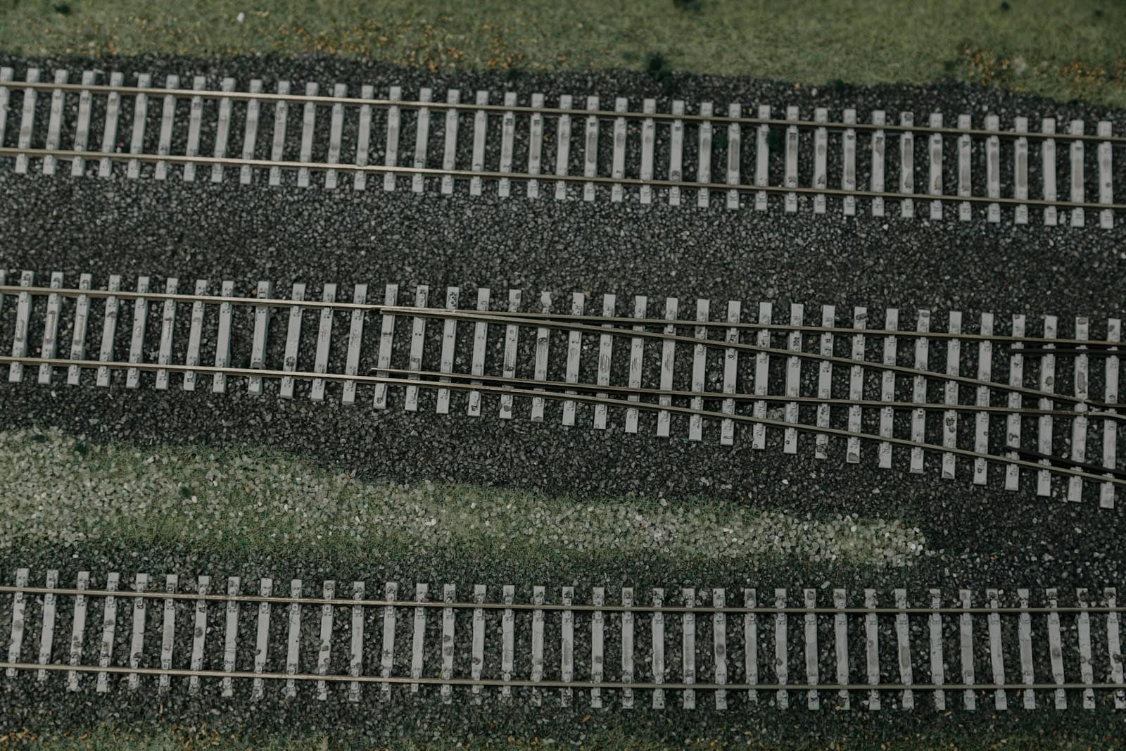
- المحاذاة:
- المبدأ: تشير المحاذاة إلى مسار السكة في المستويين الأفقي (الخطة) والعمودي (الملف الشخصي). الهدف من المحاذاة الجيدة هو إنشاء أملس وأقصر مسار ممكن مع احترام ميزات المنظر الطبيعي والقيود الأخرى. التغيرات المفاجئة في المحاذاة تعتبر مصدرًا لعدم الاستقرار وعدم الراحة.
- منحنيات الانتقال:
- المبدأ: من المستحيل ربط قسم مستقيم من السكة مباشرة بمنحنى دائري دون التسبب في تسارع جانبي مفاجئ ومزعج. لمنع ذلك، يتم إدخال منحنى انتقال، أو لولبي. الانتقال هو منحنى يتغير تدريجيًا في نصف القطر. يسمح بتغيير سلس في الاتجاه ويوفر الطول اللازم لتطبيق الميل تدريجيًا، مما يضمن دخول وخروج سلس وآمن من المنحنى الرئيسي.
- المنحدرات:
- المبدأ: المنحدر هو معدل ارتفاع أو انخفاض السكة، ويُعبر عنه عادةً بنسبة مئوية. للمنحدرات تأثير كبير على عمليات السكك الحديدية. فهي تحدد أقصى وزن يمكن للقطار أن يسحبه، وتؤثر على مسافات الكبح، وتؤثر مباشرة على استهلاك الوقود وتكاليف التشغيل.
- أمثلة على المنحدرات:
- خطوط السرعة العالية: عادةً أقل من 1.5%
- الخطوط الرئيسية التقليدية: 1% – 2%
- شحنات البضائع الثقيلة: غالبًا أقل من 1%
طرق البناء
فهم مبادئ تصميم السكة هو نصف المعادلة؛ والنصف الآخر هو فهم كيفية بناء تلك التصاميم على الأرض. تطورت عملية وضع السكك الحديثة من مهمة يدوية كثيفة العمالة إلى عملية آلية ودقيقة للغاية. هنا، نقدم مقارنة بين طرق البناء الأساسية.
الطريقة التقليدية
- نظرة عامة على العملية: الطريقة التقليدية، أو طريقة القطعة تلو الأخرى، هي النهج التقليدي لبناء السكة. العملية متسلسلة وغالبًا تعتمد على عمل يدوي كبير أو آلات صغيرة غير متخصصة.
- يتم إعداد وضغط طبقات التكوين (الأعمال الترابية) والطبقات تحت الحصوة.
- يتم توزيع الأوتاد الفردية على طول التكوين وفقًا للمسافات المحددة لها.
- يتم وضع القضبان، عادةً بأطوال أقصر، على الأوتاد وتثبيتها.
- ثم يتم رفع لوحة السكة بأكملها، ويتم إدخال الحصوة أسفلها، ويتم إجراء تمريرة تثبيت أولية لتحقيق مستوى أساسي من المحاذاة.
- حالات الاستخدام: على الرغم من بطئه، يظل هذا الأسلوب ذا صلة. وهو الأنسب لبناء مقاطع قصيرة من المسارات، والتخطيطات المعقدة مثل المفاتيح والتقاطعات، والممرات الصناعية، وفي المواقع ذات التضاريس الصعبة أو الوصول المحدود حيث لا يمكن للآلات الكبيرة العمل.
الطريقة الميكانيكية
- نظرة عامة على العملية: تستخدم الطريقة الميكانيكية آلات كبيرة ومتخصصة، مثل نظام تركيب القضبان (TLS) أو آلة بناء مسار جديد (NTC)، لتحقيق سرعة ودقة عالية. يُعرف هذا النهج بعمليته المستمرة، المشابهة للمصنع. في أكثر الطرق المستمرة شيوعًا، تقوم العربات في مقدمة قطار البناء بتغذية الأوتاد على حزام ناقل يمتد عبر الآلة، وتوضع بدقة على التشكيل المُجهز. يلي ذلك مباشرةً، خيوط طويلة من القضبان الملحومة باستمرار تُمرر من قطار القضبان، وتُوجه على الأوتاد، وتُثبت في عملية سلسة.
- وجهة نظر الموقع: مشاهدة آلة NTC حديثة أثناء العمل تجربة في التنسيق الصناعي على نطاق واسع. تتحرك الآلة، التي غالبًا ما تكون بطول مئات الأمتار، ببطء ولكن بثبات للأمام، وتستهلك المواد من القطار خلفها وتترك مسار سكة حديد كامل ودقيق في أثرها. الضوضاء هائلة، مزيج من محركات الديزل، الهيدروليكا، وحركة الصلب والخرسانة. أنظمة التوجيه بالليزر ونظام تحديد المواقع العالمي (GPS) يتحققان باستمرار من المحاذاة ويصححانها، لضمان وضع المسار بدقة تصل إلى ملليمتر من التصميم. تتطلب العملية بأكملها تنسيقًا هائلًا بين مشغلي الآلات، وفرق توريد الأوتاد والسكك، وفرق التسوية التي تتبعها مباشرة.
مقارنة الأساليب
يعتمد الاختيار بين الطرق التقليدية والميكانيكية بشكل كبير على حجم المشروع، الميزانية، والجدول الزمني. يوفر الجدول التالي مقارنة مباشرة.
| المعلمة | الطريقة التقليدية (قطعة قطعة) | الطريقة الميكانيكية المستمرة |
| سرعة البناء | بطء (مثلاً، 100-300 متر/يوم) | سريع (مثلاً، 1500-2000 متر/يوم) |
| متطلبات العمالة | مرتفعة، تتطلب الكثير من اليد العاملة | منخفضة، مشغلون مهرة جدًا |
| تكلفة رأس المال الأولية | تكلفة معدات منخفضة | تكلفة معدات عالية جدًا (آلة NTC) |
| جودة ودقة المسار | متغيرة، تعتمد على مهارة الفريق | ثابتة وعالية بشكل مستمر، وغالبًا موجهة بالليزر |
| الأفضل مناسبة لـ | الصيانة والإصلاحات<br>الجانب ومسارات الساحة<br>أراضٍ صعبة | إنشاء خط رئيسي جديد<br>مشاريع السكك الحديدية عالية السرعة<br>تجديد مسار المسافات الطويلة |
| اضطراب في حركة المرور | يمكن تنفيذها في فترات عمل قصيرة | تتطلب احتجازات طويلة للمسار (حواجز) |
العلم المخفي
بينما القضبان والأوتاد هي الوجه الظاهر للسكك الحديدية، فإن الاستقرار والأداء طويل الأمد للخط يعتمد تمامًا على العلم المخفي للهندسة الأرضية. الأساس — المكون من الأرض أدناه والحصى — هو العنصر الأكثر أهمية في الهيكل بأكمله. الفشل هنا مكلف وصعب الإصلاح.
دور الأرض أدناه
- مبدأ توزيع الأحمال: يُمارس عجلة القطار ضغط اتصال عالي جدًا على السكة. الهدف من هيكل المسار هو توزيع هذا الحمل المركز على مساحة كافية بحيث يمكن للأرض الأساسية أن تدعمه دون أن تتشوه. ينتشر الحمل من السكة، عبر الأوتاد، عبر الحصى، وأخيرًا على الأرض أدناه. كل طبقة تقلل الضغط، لذا فإن الإجهاد النهائي على الأرض الطبيعية هو جزء صغير جدًا من ضغط الاتصال الأولي.
- تقييم الأرض: قبل وضع أي مسار، من الضروري إجراء تحقيق شامل في الأرض أدناه. يقيم المهندسون نوع التربة، محتوى الرطوبة، وإمكانية الاستقرار. أهم معلمة هي قوة التربة، وغالبًا ما تُقاس بواسطة اختبار نسبة التحمل بكاليفورنيا (CBR). قيمة CBR منخفضة تشير إلى أرض ضعيفة ستتطلب تحسينًا كبيرًا للأرض — مثل التثبيت أو إضافة طبقة تغطية — لتوفير أساس مستقر للمسار.
الحصى: أكثر من مجرد حجارة
قد تبدو طبقة الحصى ككومة بسيطة من الحجارة، لكنها طبقة هندسية ذات وظيفة عالية مصممة لأداء عدة مهام حاسمة في آن واحد.
- الدور المتعدد الاستخدامات لطبقة الحصى:
- توزيع الأحمال: يوزع الأحمال العالية من الأوتاد بشكل متساوٍ عبر الأرض أدناه.
- الصرف: الفراغات الكبيرة بين الحجارة الزاوية ضرورية للسماح بتصريف مياه الأمطار بسرعة بعيدًا عن هيكل المسار. إذا تم حبس الماء، يمكن أن يضعف الأرض أدناه، مما يؤدي إلى عدم استقرار المسار.
- المرونة وامتصاص الصدمات: توفر طبقة الحجارة غير المرتبة درجة من المرونة، وتمتص الصدمات والاهتزازات من القطارات المارة. هذا يقلل من تآكل مكونات المسار الأخرى ويقلل من الضوضاء الناتجة عن الأرض.
- التثبيت: يوفر تداخل الحجارة الزاوية مقاومة قوية للقوى الجانبية، الرأسية، والطولية التي يفرضها القطارات، مما يثبت لوحة المسار في مكانها بشكل فعال.
- القابلية للتعديل: الحصى هو المفتاح للحفاظ على هندسة المسار. يمكن لآلات التمشيط رفع المسار بدقة وإعادة ترتيب الحصى تحته لتصحيح مشاكل الاستقرار والمحاذاة على مدى عمر المسار.
- تدهور الحصى: مع مرور الوقت، يتدهور الحصى. تتآكل الزوايا الحادة للحجارة تحت الحمل، وتتلوث الطبقة بجزيئات دقيقة من القطع، والأرضية أدناه، والبيئة. تُعرف هذه العملية بالتلوث، وتسد الفراغات، مما يعيق التصريف بشكل كبير ويقلل من قوة التداخل. عندما يصل التلوث إلى مستوى حرج، يجب تنظيف الحصى بواسطة آلات متخصصة أو إزالته واستبداله بالكامل.
ضمان الدقة
وضع السكة الحديدية هو مجرد جزء من المهمة. المرحلة النهائية والحاسمة تتضمن عملية دقيقة من التعديلات، والتشطيب، ومراقبة الجودة لضمان أن تلبي السكة الجديدة المعايير الدقيقة المطلوبة لعمليات السكك الحديدية الحديثة. تعتمد هذه المرحلة على التكنولوجيا المتقدمة والقياسات الدقيقة.
تكنولوجيا البناء الحديثة
- الضغط الآلي والتوجيه: بعد إسقاط الحصى الأولي، تكون هندسة السكة بعيدة عن الكمال. آلات الضغط الحديثة هي مركبات متطورة للغاية تصحح ذلك. تستخدم أنظمة توجيه ليزرية أو بصرية مرجعية لنقاط المسح الثابتة. تغوص شوكات الآلة في الحصى على جانبي قطعة النوم، وتهتز لتسييل الحجارة مع رفع وتحريك لوحة السكة بدقة إلى إحداثيات التصميم الخاصة بها. ثم تضغط الشوكات على الحصى بقوة تحت قطعة النوم، وتثبتها في مكانها.
- تقنيات لحام السكك الحديدية:
- مبدأ السكك الملحومة المستمرة (CWR): كان صوت
- طرق اللحام: الطريقتان الرئيسيتان لإنشاء CWR في الميدان هما اللحام بالتيرميت واللحام بالوميض-الضغط. اللحام بالتيرميت هو عملية محمولة تستخدم تفاعل كيميائي لإنتاج فولاذ منصهر يملأ الفجوة بين طرفي السكة. اللحام بالوميض-الضغط هو عملية آلية عالية الجودة يتم فيها تمرير تيار كهربائي قوي عبر نهايتي السكة، مما يسخنها إلى درجة التشكيل قبل أن يتم دفعها معًا لتشكيل لحام. عادةً يتم ذلك في مستودع أو باستخدام آلة لحام متنقلة مثبتة على السكة.
قائمة فحص مراقبة الجودة
بمجرد الانتهاء من البناء، يتم إجراء سلسلة من الفحوصات الصارمة لاعتماد أن السكة صالحة للخدمة. التفاوتات ضيقة جدًا، خاصة للخطوط عالية السرعة حيث يمكن أن يكون للاختلافات الصغيرة تأثيرات كبيرة على السلامة.
| المعلمة التي يتم فحصها | أداة/نظام القياس | التحمل النموذجي (خط عالي السرعة) | عاقبة الانحراف |
| مقياس السكة | مقياس العربة، مركبة التسجيل | ± 1.5 مم | خطر الانحراف عن المسار، رحلة غير مستقرة |
| غير قادر (المصرفية) | أداة قياس القدرة الرقمية | ± 2 ملم | راحة الركاب السيئة، تآكل غير متساوٍ للعجلات |
| التواء (تغير مستوى العرض) | يتم القياس على قاعدة محددة (مثلاً 3م) | < 1 في 1500 | خطر عالي من تفريغ العجلات / الانحراف عن المسار |
| المحاذاة الأفقية والرأسية | مركبة تسجيل المسار، أنظمة الليزر | ± 2 ملم على طول وتر 10م | جودة ركوب سيئة، زيادة الاهتزازات |
| تكثيف الحصى | مُثبت المسار الديناميكي، اختبارات الكثافة | يختلف حسب المواصفات | خطر تدهور الهندسة بسرعة |
| سلامة اللحام | الكشف بالموجات فوق الصوتية عن العيوب | خالية من العيوب | خطر كسر قضيب السكك الحديدية الكارثي |
الخاتمة: العلم والممارسة
لقد استعرضت هذه الرحلة من علم المواد الخاص بقطار واحد إلى اللوجستيات على نطاق واسع للبناء الميكانيكي. لقد رأينا كيف أن تركيب القضبان يتجاوز مجرد وضع الصلب على الأرض. إنه مزيج متطور من الهندسة المدنية والأرضية، الفيزياء التطبيقية، وعلوم المواد. من المكونات الأساسية المصممة لإدارة قوى هائلة، إلى المبادئ الهندسية التي توجه المركبات بأمان بسرعة، وأخيرًا التكنولوجيا المتقدمة ومراقبة الجودة التي تضمن دقة الملليمتر، كل خطوة حاسمة. المنتج النهائي — سكة حديد حديثة — هو شهادة على هذا المزيج من العلم والممارسة، جميعها تعمل معًا لتقديم شبكات نقل آمنة وموثوقة وفعالة تدعم اقتصادياتنا.
- https://arema.org/ الجمعية الأمريكية لهندسة السكك الحديدية وصيانة الطرق
- https://www.uic.org/ الاتحاد الدولي للسكك الحديدية (UIC)
- https://en.wikipedia.org/wiki/Track_ballast ويكيبيديا – حجر الترصيف للسكك الحديدية
- https://railroads.dot.gov/ إدارة السكك الحديدية الفيدرالية (FRA)
- https://www.sciencedirect.com/ ScienceDirect – أبحاث هندسة السكك الحديدية
- https://www.rssb.co.uk/ مجلس سلامة ومعايير السكك الحديدية (RSSB)
- https://www.up.com/ اتحاد بكينك – معايير هندسة القضبان
- https://www.bnsf.com/ BNSF للسكك الحديدية – إرشادات بناء القضبان
- https://www.researchgate.net/ ResearchGate – أبحاث معايير السكك الحديدية
- https://www.iso.org/ ISO – المعايير الدولية للسكك الحديدية


