Understanding How Metal Cutting Works: A Complete Guide to the Basic Principles
Introduction: Moving from How to Why
Cutting metal is one thing; truly understanding how it works is something completely different. For today’s engineers, machinists, and process planners, knowing just the basic speeds and feeds is no longer enough. To become truly skilled, you need to move beyond just knowing “how” to do something and understand the “why”—the basic physics that control how a solid piece of metal becomes a precisely finished part and a stream of metal chips.
Understanding these principios básicos is what separates regular work from expert-level manufacturing. It’s the foundation for making processes better, quickly and accurately fixing problems, and creating parts with excellent surface quality. Without this knowledge, improving processes becomes guesswork rather than a predictable, engineered result. This article breaks down the metal cutting process from a scientific viewpoint. We will explore the first moment when material breaks apart, analyze the forces and heat involved, diagnose how tools wear out, and finally, examine the technical marks left on the workpiece surface.
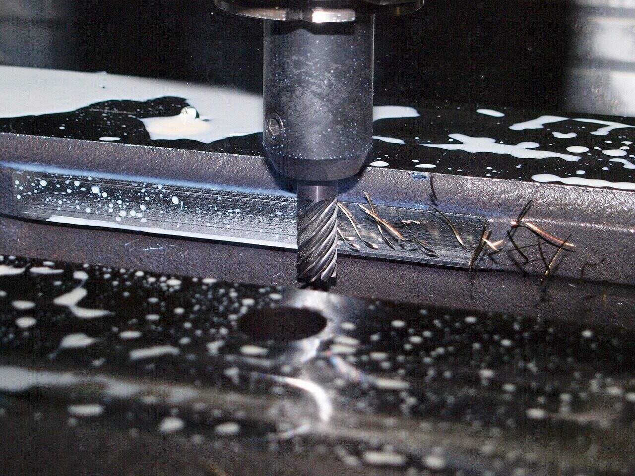
The Physics of Chip Formation
The most important event in any metal cutting process is the formation of a chip. This isn’t a simple slicing action but a complex process of intense, localized plastic deformation. To understand cutting, we must first understand how a small volume of workpiece material is sheared away from the main body. Picture the cutting tool moving into the workpiece. The material in front of the tool gets compressed, creating enormous stress. When this stress becomes greater than the material’s shear strength, it deforms and slides along a specific plane, known as the shear plane. This action, happening continuously, forms the chip.
Shear Zone and Shear Plane
The area of intense plastic deformation where the workpiece material transforms into a chip is called the primary shear zone. This zone is simplified as a single, thin plane—the shear plane—which starts at the cutting edge and extends to the free surface of the workpiece. The angle this plane makes with the direction of cutting velocity is the shear angle (φ).
The shear angle is an extremely important variable. A larger shear angle results in a shorter shear plane and a thinner chip. This means less material is being deformed at any given moment, which directly leads to lower cutting forces, reduced power use, and less heat generation. Therefore, a larger shear angle is almost always better for efficient machining. The shear angle isn’t fixed but is influenced by several factors, most notably the tool’s rake angle and the coefficient of friction between the chip and the tool face.
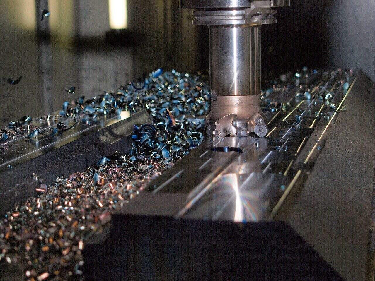
Types of Chips and How They Form
The type of chip produced during an operation isn’t random; it’s a direct indicator of the cutting conditions. By looking at the chip, a skilled engineer can figure out information about how efficient the process is, the condition of the tool, and whether the selected parameters are appropriate. How the chip forms determines its shape, which has significant effects on the machining operation. Different materials and cutting conditions produce distinct chip types, each with its own characteristics and what they reveal about the process.
| Chip Type | How It Forms | Materiales típicos | What It Means for Machining |
| Continuous Chip | Smooth, continuous plastic deformation in the primary shear zone. | Ductile materials (e.g., low-carbon steel, aluminum) | Good surface finish, steady cutting forces, but can cause handling problems (long, stringy chips). |
| Discontinuous Chip | Material breaks into segments due to low ductility or high friction. | Brittle materials (e.g., hierro fundido) or very low cutting speeds. | Good chip breakability, but can lead to changing forces and a poorer surface finish. |
| Continuous with Built-Up Edge (BUE) | Layers of workpiece material stick and weld to the tool face, then break off. | Ductile materials at medium cutting speeds. | Protects the cutting edge but periodically breaks off, making surface finish worse and causing wear. |
Analyzing Forces in Cutting
Every metal cutting operation involves a system of forces acting on the tool and the workpiece. Understanding this system quantitatively is essential for predicting power consumption, designing strong fixtures, analyzing process stability, and preventing tool failure. These forces come from the energy required to shear the material in the primary shear zone and the frictional energy used as the chip slides across the tool’s rake face. Measuring and analyzing these forces provides insight into how efficient and stable the cutting process is.
The Cutting Force System
The complex force system can be simplified and broken down into perpendicular components for practical analysis. The primary forces of interest are:
- Cutting Force (Fc): This is the main and typically largest force component. It acts in the direction of the cutting velocity. The size of the cutting force, multiplied by the cutting speed, determines the power required to perform the cut. It is the primary factor in calculating the machine tool’s power consumption.
- Thrust Force (Ft): Also known as the feed force, this component acts perpendicular to the cutting velocity, in the direction of tool feed. While it contributes less to power consumption, the thrust force is critical for dimensional accuracy. High thrust forces can cause bending of the tool, workpiece, or machine components, leading to dimensional errors and potential vibration.
- Resultant Force (R): This is the vector sum of the cutting force and the thrust force. It represents the total load placed on the cutting tool and must be handled by the tool holder, spindle, and machine structure.
The Merchant Circle Diagram
cURL Too many subrequests.
cURL Too many subrequests.
- cURL Too many subrequests.
- cURL Too many subrequests.
- cURL Too many subrequests.
cURL Too many subrequests.
cURL Too many subrequests.
cURL Too many subrequests. cURL Too many subrequests.cURL Too many subrequests. cURL Too many subrequests.cURL Too many subrequests.
cURL Too many subrequests.
cURL Too many subrequests.
- cURL Too many subrequests.
- cURL Too many subrequests.
- cURL Too many subrequests.
cURL Too many subrequests.
cURL Too many subrequests.
cURL Too many subrequests.
- cURL Too many subrequests.
- cURL Too many subrequests.
- cURL Too many subrequests.
- cURL Too many subrequests.
cURL Too many subrequests.
cURL Too many subrequests.
cURL Too many subrequests.
cURL Too many subrequests.
- cURL Too many subrequests.
- cURL Too many subrequests.
- cURL Too many subrequests.
- cURL Too many subrequests.
cURL Too many subrequests.
cURL Too many subrequests. acero inoxidable cURL Too many subrequests.
| cURL Too many subrequests. | Descripción | cURL Too many subrequests. | cURL Too many subrequests. |
| cURL Too many subrequests. | cURL Too many subrequests. | cURL Too many subrequests. | cURL Too many subrequests. |
| Adhesión | Micro-welding between the chip and tool, followed by fracture, pulling away tool material. Associated with BUE. | Low-to-medium speeds; high affinity between tool/work materials. | Increase cutting speed, use effective coatings (e.g., TiN), improve lubrication. |
| Diffusion | Atoms from the tool material move into the chip (and vice-versa) due to high temperatures, weakening the tool. | High cutting speeds, especially when machining steel and nickel alloys. | Use chemically stable tool materials (ceramics, CBN) or advanced coatings (e.g., Al2O3). |
| Fatiga | Cracking caused by repeated mechanical or thermal stresses, common in interrupted cuts like milling. | Interrupted cutting operations (milling). | Use a tougher tool grade, optimize tool path to ensure smooth entry/exit. |
Surface Integrity: The Technical Footprint
The final goal of metal cutting is not just to achieve a specific dimension but also to produce a surface with the required functional performance. Surface integrity is a comprehensive term that describes the quality and character of the surface and subsurface layer of a machined component. It extends far beyond simple appearance or roughness, including the mechanical and metallurgical properties that determine the part’s performance in its service environment. The cutting mechanics directly create a technical footprint onto this surface.
Defining Surface Integrity
Surface integrity is a multi-faceted concept that includes several key components:
- Surface Finish/Roughness: This refers to the fine-scale topography or texture of the surface, typically measured in Ra or Rz. It is primarily determined by the tool’s geometry and the feed rate.
- Microstructural Changes: The intense deformation and heat of cutting can alter the grain structure of the material just below the surface. This can include plastic deformation, phase transformations, or the formation of a very hard, brittle “white layer.”
- Residual Stresses: These are stresses that remain locked within the surface layer of the material after the cutting process is complete and all external loads are removed.
Understanding Residual Stress
The state of residual stress in a finished component is a critical, yet often overlooked, aspect of surface integrity. These internal stresses can significantly impact a part’s fatigue life, corrosion resistance, and dimensional stability. Residual stresses are the result of a competition between two opposing effects:
- Mechanical Effect: The plowing and burnishing action of the cutting tool nose radius plastically deforms the surface layer. This action tends to create compressive residual stress, which is generally beneficial as it can prevent the start and spread of fatigue cracks.
- Thermal Effect: The intense, localized heating of the surface by the cutting process, followed by rapid cooling (quenching) by the surrounding material and coolant, tends to create tensile residual stress. Tensile stresses are harmful as they can promote crack formation and reduce fatigue life.
The final stress state is the net result of this battle. Sharp tools, larger nose radii, and moderate cutting parameters tend to favor the mechanical effect, producing beneficial compressive stresses. Conversely, worn tools and aggressive, high-temperature cutting can cause the thermal effect to dominate, leaving behind dangerous tensile stresses in the component.
Controlling Integrity via Parameters
The final surface integrity is not an accident; it is an engineered result. By carefully selecting cutting parameters, we can control the mechanical and thermal effects to achieve the desired surface characteristics.
| Parámetro | Effect on Surface Roughness | Effect on Residual Stress |
| Cutting Speed | Generally improves (decreases roughness) up to a point, beyond which tool wear dominates. | Tends to increase tensile stress due to higher thermal effects. |
| Feed Rate | Major influence; higher feed directly increases the theoretical roughness. | Can increase compressive stress due to higher mechanical load, but can also cause more surface damage. |
| Tool Nose Radius | A larger radius generally improves finish by smoothing the feed marks. | A larger radius increases the burnishing action, strongly promoting beneficial compressive stress. |
| Tool Wear | Worn tools drastically increase roughness and can tear the surface. | Worn tools increase both thermal and mechanical loads, often leading to a shift towards harmful tensile stress. |
cURL Too many subrequests.
cURL Too many subrequests.
cURL Too many subrequests.
- Galvanoplastia - Wikipedia https://en.wikipedia.org/wiki/Electroplating
- Anodizado - Wikipedia https://en.wikipedia.org/wiki/Anodizing
- ScienceDirect Topics - Tratamiento electroquímico de superficies https://www.sciencedirect.com/topics/materials-science/electrochemical-surface-treatment
- ASTM International - Normas de tratamiento de superficies https://www.astm.org/
- Asociación para la Protección y el Rendimiento de los Materiales (AMPP) https://ampp.org/
- ASM International - Ingeniería de superficies https://www.asminternational.org/
- NIST - Ciencia de la medición de materiales https://www.nist.gov/mml
- SpringerLink - Tecnología de superficies y revestimientos https://link.springer.com/journal/11998
- Materiales hoy - Ingeniería de superficies https://www.materialstoday.com/
- SAE International - Normas de tratamiento de superficies https://www.sae.org/


