Guía del maquinista para el ajuste del ancho de vía: Comprender los conceptos básicos y las mejores prácticas
Introducción: Por qué es importante la precisión
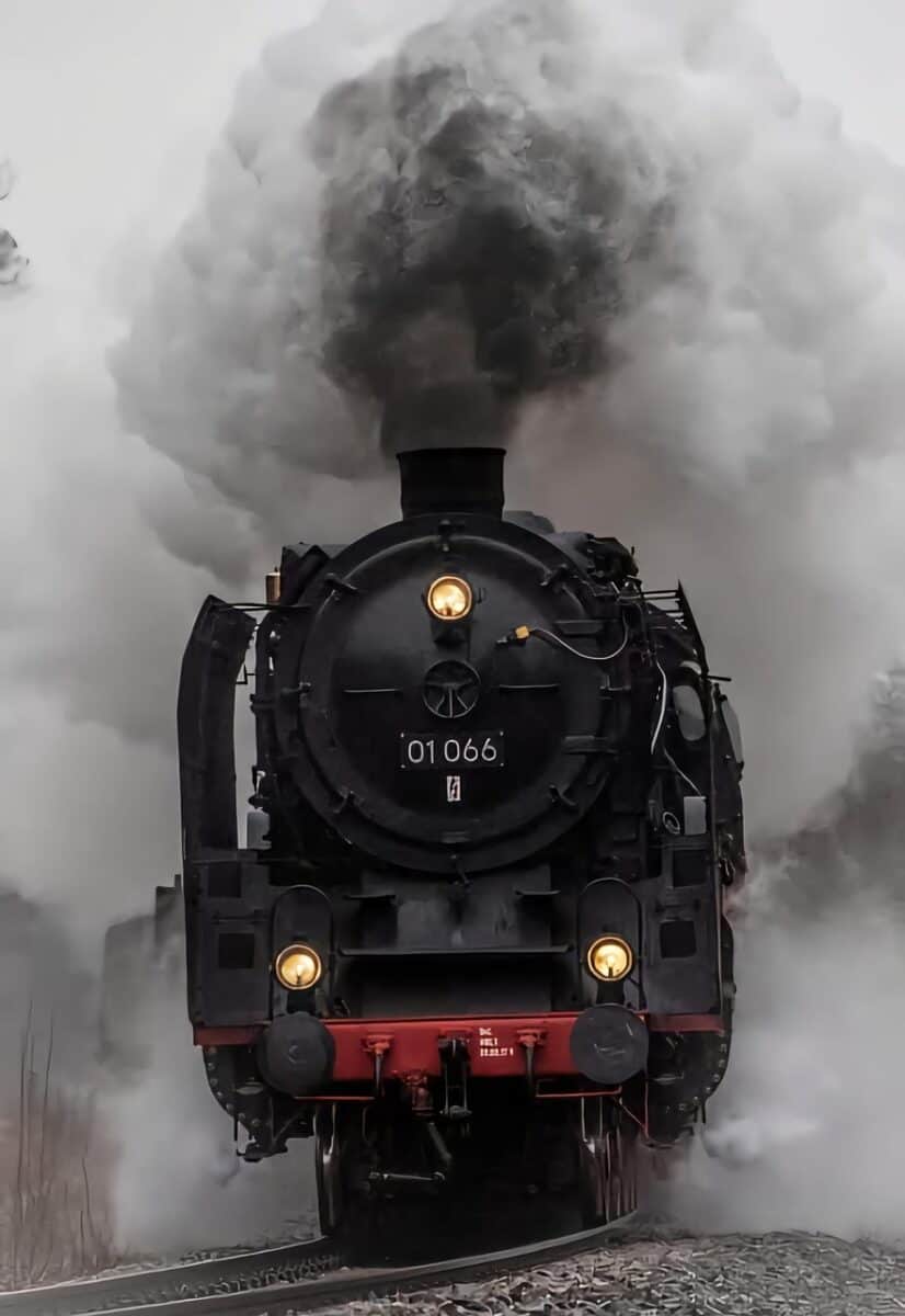
En ingeniería ferroviaria, el ancho de vía es la distancia exacta entre las caras interiores de dos carriles. Esta medida es crucial para la seguridad, el buen funcionamiento y el mantenimiento de las vías y los trenes en buenas condiciones. El ancho de vía estándar utilizado en la mayoría de los ferrocarriles del mundo es de 1.435 mm. Incluso pequeños cambios de esta norma, medida en milímetros, pueden causar problemas como inestabilidad, desgaste más rápido de las piezas, límites de velocidad y, en el peor de los casos, descarrilamientos de trenes.
Comprender el ajuste del ancho de vía es algo más que una labor de mantenimiento: es una importante habilidad técnica. Esta guía ofrece a los maquinistas y trabajadores ferroviarios una visión técnica completa. Desglosaremos la ciencia básica, identificaremos las causas de los problemas de ancho de vía, estudiaremos los distintos métodos de ajuste, desde el manual hasta el automatizado, y explicaremos los procesos de comprobación que garantizan una precisión y seguridad duraderas en las redes ferroviarias.
Funcionamiento conjunto de ruedas y raíles
Para gestionar correctamente el ancho de vía, primero hay que entender cómo interactúan las ruedas y los raíles. El sistema está diseñado para guiarse a sí mismo, basándose en cómo está conformado el juego de ruedas.
La idea clave es la forma de la rueda. Las ruedas de ferrocarril no son cilindros planos, sino que tienen forma de conos cortados, con un diámetro en la pestaña ligeramente mayor que el diámetro en el borde exterior de la rueda. Cuando un juego de ruedas está perfectamente centrado en una vía recta, ambas ruedas ruedan la misma distancia. Si el juego de ruedas se desplaza lateralmente, por ejemplo hacia la derecha, la rueda derecha toca el carril con un diámetro mayor, mientras que la izquierda lo hace con un diámetro menor. Esto hace que la rueda derecha recorra más distancia por vuelta que la izquierda, dirigiendo naturalmente el juego de ruedas de vuelta al centro. Esta acción de autocentrado es esencial para un funcionamiento estable del tren.
El ancho de vía correcto es la base que permite que este sistema funcione dentro de unos límites seguros. Son varias las fuerzas que actúan constantemente, y la estructura de la vía debe hacerles frente:
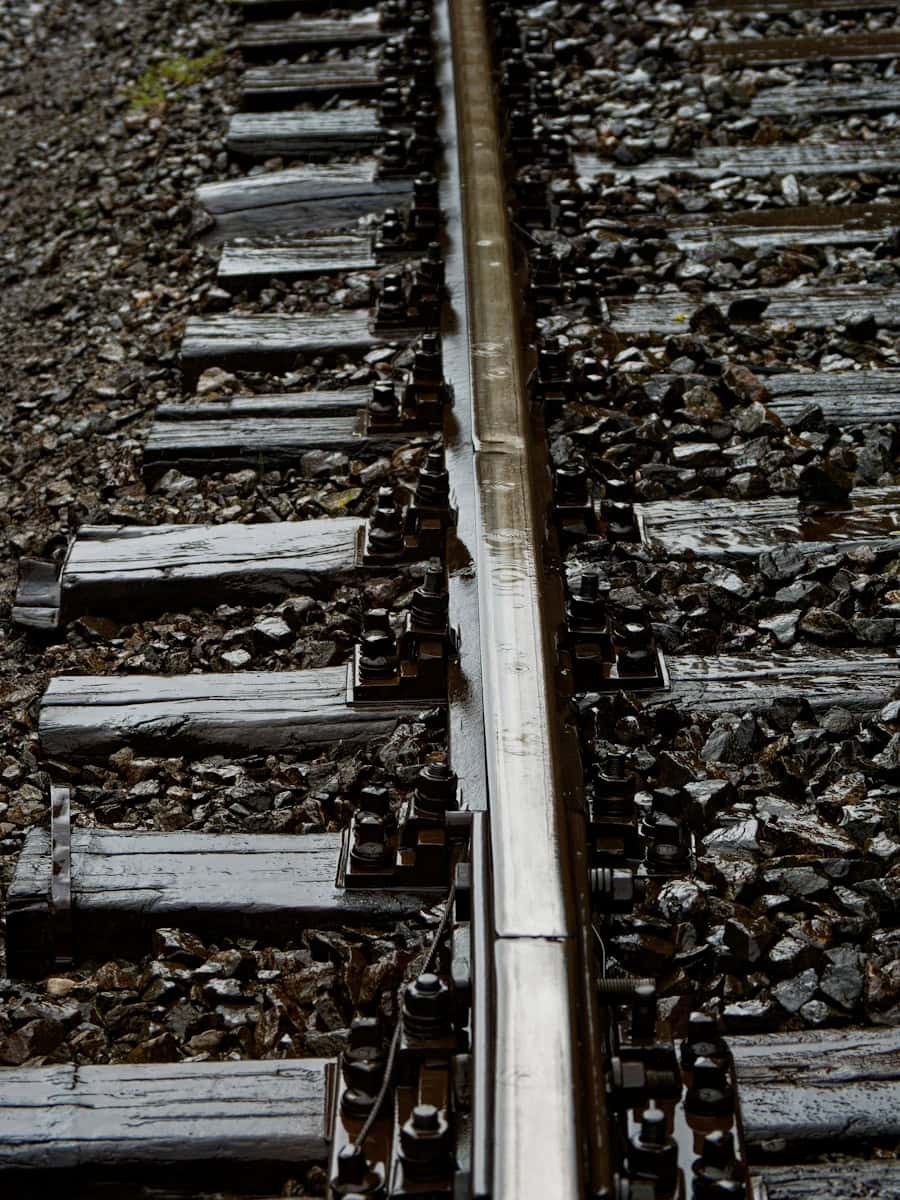
- Cargas verticales: Son las principales fuerzas descendentes del peso del tren. Atraviesan el carril, el sistema de fijación, las traviesas y el balasto hasta llegar al suelo. Un gálibo incorrecto puede provocar cargas desiguales, sometiendo a las piezas a esfuerzos desiguales.
- Fuerzas laterales: Son fuerzas que actúan de lado a lado. Una fuente principal es el movimiento de vaivén, un movimiento natural de vaivén del juego de ruedas cuando encuentra su centro. Aunque es normal en las ruedas cónicas, un movimiento demasiado brusco causado por un calibre incorrecto o superficies desgastadas puede provocar inestabilidad y un gran desgaste.
- Fuerza centrífuga: En las vías curvas, el peso del tren empuja hacia fuera. Esta fuerza se equilibra con la inclinación de la vía y la resistencia lateral de la estructura de la vía, principalmente el carril alto. Esta fuerza suele provocar un ensanchamiento del ancho de vía.
- Fuerzas térmicas: Los raíles de acero se dilatan y contraen considerablemente con los cambios de temperatura. En los carriles soldados en continuo, estas fuerzas son enormes y deben ser controladas por el sistema de fijación y el peso de las traviesas. Las fuerzas térmicas pueden provocar un estrechamiento del gálibo y, lo que es más grave, el pandeo de la vía.
Organizaciones como la Asociación Americana de Ingeniería Ferroviaria y Mantenimiento de Vías (AREMA) y la Unión Internacional de Ferrocarriles (UIC) establecen estrictos márgenes de tolerancia para el ancho de vía, a menudo dentro de unos pocos milímetros del valor estándar, para garantizar que estas fuerzas se gestionan de forma segura.

Comprender los problemas de los manómetros
El ancho de vía no permanece invariable. Cambia con el tiempo debido al estrés operativo y a factores ambientales. Encontrar la causa de un problema es el primer paso para solucionarlo eficazmente. Los problemas se clasifican principalmente en ensanchamiento o estrechamiento del ancho de vía.
Causas del ensanchamiento del ancho de vía
El ensanchamiento del ancho de vía es el problema más común, cuando la distancia entre carriles supera la tolerancia permitida. Es un fallo gradual que reduce la capacidad de autocentrado de la rueda y aumenta el riesgo de que una rueda "caiga" entre los raíles.
- Desgaste de raíles y fijaciones: En las curvas, la fuerza centrífuga presiona las pestañas de las ruedas contra la cara del ancho de vía del carril alto. Esto provoca el desgaste, reduciendo gradualmente el tamaño de la cabeza del carril y ensanchando efectivamente el ancho de vía. Al mismo tiempo, las fuerzas laterales pueden causar desgaste y aflojamiento en las piezas de fijación como clips, espigas y aisladores.
- Problemas con las traviesas: Las traviesas son las piezas principales que mantienen los raíles en el gálibo correcto. En las traviesas de madera, la humedad puede causar podredumbre, especialmente alrededor de los agujeros de los clavos, reduciendo su capacidad para resistir fuerzas laterales. Las espigas pueden aflojarse, dejando que el carril se incline hacia fuera. En las traviesas de hormigón, el agrietamiento o los daños en el hombro incorporado o en el inserto de fijación pueden provocar la pérdida de la capacidad de mantener el gálibo.
- Cuestiones de cimentación y balasto: La capa de balasto distribuye las cargas y proporciona resistencia lateral a la vía. Cuando el balasto se ensucia con partículas finas (polvo de carbón, suciedad, arena), pierde sus propiedades de agarre y su capacidad de drenaje. Esto provoca una acción de "bombeo" bajo carga, el asentamiento de la vía y la pérdida de estabilidad lateral, lo que permite que toda la sección de la vía se extienda.
Causas del estrechamiento del ancho de vía
El estrechamiento del gálibo es menos frecuente, pero puede ser igualmente peligroso, ya que aumenta el riesgo de que la pestaña de una rueda trepe por el raíl, lo que puede provocar directamente un descarrilamiento.
- Contracción térmica: En climas muy fríos, la contracción longitudinal de los carriles puede, en algunas configuraciones de vía y fijación, tirar hacia dentro, provocando un ligero estrechamiento del gálibo. Sin embargo, el mayor riesgo térmico es el pandeo por dilatación, que puede manifestarse como una fuerte desalineación local que incluya un estrechamiento del ancho de vía.
- Instalación o ajuste incorrectos: Los errores humanos durante la construcción o el mantenimiento de la vía son una causa importante. El exceso de clavos, el ajuste incorrecto del ancho de vía durante el reencarrilado o los ajustes defectuosos de una bateadora pueden crear condiciones de ancho de vía estrecho.
- Flujo del carril/Deformación plástica: En el carril bajo de una curva cerrada con tráfico pesado y lento, las altas tensiones de contacto pueden hacer que el acero de la cabeza del carril "fluya" o se doble permanentemente hacia el lado del gálibo. Esta acumulación de material estrecha efectivamente el gálibo y puede crear una rampa peligrosa para la pestaña de la rueda.
| Causa | Ubicación típica | Efecto primario | Consecuencia si no se marca |
| Desgaste de la cabeza del raíl | Carril alto en curvas | Ensanchamiento del gálibo | Aumento de la caza, riesgo de caída de la rueda |
| Degradación de las traviesas | En cualquier lugar, especialmente en zonas húmedas | Ensanchamiento del gálibo | Pérdida de estabilidad de la vía, fallo de la fijación |
| Ensuciamiento del lastre | En cualquier lugar, especialmente con mal drenaje | Ensanchamiento/irregularidad del gálibo | Mala distribución de la carga, deterioro acelerado de la vía |
| Flujo ferroviario | Carril bajo en curvas | Estrechamiento del gálibo | Aumento de la fricción, riesgo de escalada de la rueda |
| Expansión térmica | Tangentes, secciones CWR | Estrechamiento del gálibo (pandeo) | Abombamiento catastrófico de la vía, descarrilamiento |
Una inmersión técnica
Los métodos de ajuste del ancho de vía van desde las técnicas manuales básicas hasta los sistemas automatizados más avanzados. La elección del método depende de la magnitud del problema, el tipo de construcción de la vía y los recursos disponibles.
Técnicas manuales y semimanuales
Para reparaciones puntuales, trabajos en espacios reducidos o en líneas secundarias, los métodos manuales siguen siendo útiles. Estas técnicas dependen de la fuerza física y de la habilidad del personal de vía.
El proceso suele implicar el uso de una barra calibradora, una barra calibrada con un dial de medición, para encontrar la ubicación exacta y el tamaño del problema. Para arreglar los ensanchamientos de vía en vías con traviesas de madera, el personal utiliza barras de garra para tirar de las espigas en el lado de campo de un carril. A continuación, utilizan palancas pesadas, o un separador hidráulico de carriles, para apalancar el carril hacia el interior hasta el gálibo correcto. A continuación, se introducen nuevos clavos en los nuevos orificios.
Por experiencia, este proceso requiere buen juicio. Conseguir una precisión milimétrica con una palanca es difícil y físicamente exigente. Con el tiempo se aprende a "sentir" hasta qué punto el raíl retrocede cuando se libera la fuerza. Una buena práctica importante es utilizar un patrón escalonado al volver a clavar los clavos; tirar y volver a clavar todos los clavos en varias traviesas consecutivas crea un punto débil en la sección de la vía. Al escalonar el trabajo, se mantiene mejor la resistencia lateral de la vía.
Ajuste mecanizado del bateo
Para el mantenimiento de la línea principal, la eficiencia y la precisión requieren mecanización. Las bateadoras modernas, como las de Plasser & Theurer o Harsco, son plataformas multifunción que combinan elevación, revestimiento, bateo y ajuste de gálibo en un único proceso automatizado.
La capacidad de ajuste del gálibo de estas máquinas es un impresionante ejemplo de ingeniería. El sistema funciona según un principio de control de bucle cerrado:
- Medición: Un bastidor de medición montado en la parte delantera, a menudo equipado con sensores láser u ópticos sin contacto, se desplaza por delante de la unidad de trabajo principal. Mide con precisión la geometría de la vía existente, incluido el gálibo de cada traviesa.
- Cálculo: Estos datos se transmiten a un ordenador de a bordo. El ordenador compara el gálibo medido con el archivo de geometría de diseño para esa sección de vía específica, calculando la corrección exacta necesaria.
- Acción: Cuando la parte principal del pisón llega a la traviesa, un conjunto de cilindros hidráulicos y pinzas de rodillos agarran los raíles. Guiado por los cálculos del ordenador, el sistema hidráulico aplica una fuerza lateral precisa, empujando o tirando de los raíles hasta la posición de gálibo objetivo.
- Fijación: Mientras los carriles se mantienen firmemente en esta posición corregida, las unidades de bateo se ponen en marcha. Sus púas vibrantes se introducen en el balasto a ambos lados de la traviesa y lo compactan firmemente por debajo, fijando la traviesa -y por tanto el ancho de vía- en su nueva posición correcta.
Este enfoque integrado y automatizado proporciona un nivel de precisión y coherencia que no puede lograrse con métodos manuales, garantizando el cumplimiento de las estrictas tolerancias necesarias para el funcionamiento a alta velocidad.
Una solución diferente: VGA
Mientras que la mayor parte de este debate se centra en el ajuste de la vía para que se adapte al tren, un enfoque de ingeniería alternativo ajusta el tren para que se adapte a la vía. Se trata de los ejes de ancho variable (VGA), también conocidos como ejes intercambiables. Estos sistemas son una solución innovadora a otro tipo de problema de ancho de vía: la circulación de un mismo tren por redes con diferentes anchos de vía. Se trata de un requisito habitual en Europa, por ejemplo, en la frontera entre España (ancho de vía de 1668 mm) y Francia (ancho de vía de 1435 mm).
El principal reto de ingeniería consiste en diseñar un juego de ruedas que pueda bloquearse de forma segura en un ancho de vía para un funcionamiento seguro y, a continuación, desbloquearse, trasladarse a un nuevo ancho de vía y volver a bloquearse con total fiabilidad. El proceso se realiza en una instalación especial en tierra conocida como cambiador de ancho. A medida que el tren lo atraviesa lentamente, los carriles guía enganchan las ruedas. Se activa un mecanismo de desbloqueo en el eje, lo que permite que las ruedas se deslicen lateralmente a lo largo del eje hasta que alcanzan el nuevo ancho de vía, momento en el que se vuelve a activar un mecanismo de bloqueo.
Se han desarrollado varios diseños competidores, cada uno con un enfoque diferente del mecanismo de bloqueo crítico.
| Nombre del sistema | País de origen | Mecanismo de bloqueo | Característica principal |
| Talgo RD | España | Pernos/pasadores mecánicos | Pasivo, se basa en rampas en tierra; probado y ampliamente utilizado en el servicio de pasajeros. |
| RSU 2000 | Polonia | Manguito de cierre centralizado | Puede utilizarse en vagones de mercancías; diseño robusto adecuado para cargas por eje más pesadas. |
| DBAG/Relleno Tipo V | Alemania | Sistema de bayoneta con bloqueo de forma | Diseñado para funcionar a alta velocidad; complejo pero ofrece gran precisión y redundancia. |
La tecnología VGA muestra un enfoque completo del "problema del ancho de vía", demostrando cómo la ingeniería innovadora de los vehículos puede aportar soluciones que complementen el mantenimiento y el ajuste tradicionales de las vías.
Verificación y control de calidad
El ajuste del ancho de vía está incompleto sin un proceso de comprobación exhaustivo. Corregir el ancho de vía es sólo la mitad del trabajo; confirmar que la corrección es precisa, estable y cumple las normas es esencial para garantizar la seguridad y obtener los beneficios del trabajo. El control de calidad se basa en diferentes tecnologías de medición.
La elección de la herramienta depende del contexto del trabajo. Una pequeña cuadrilla que realiza una reparación manual puntual utilizará una herramienta distinta a la de un gran gestor de infraestructuras que comprueba el estado de un corredor de cien kilómetros.
| Herramienta / Tecnología | Cómo funciona | Precisión | Caso práctico |
| Manómetro manual (carro) | Barra mecánica con lector dial/digital | ~0,5 mm | Controles puntuales, verificación inmediata tras el ajuste, trabajo a pequeña escala. |
| Sistemas ópticos sin contacto | Medición por láser o cámara | ~0,1 - 0,3 mm | Montado en bateadoras para el control en tiempo real o en vehículos de registro específicos. |
| Unidad de medición inercial (IMU) | Acelerómetros y giroscopios en un carro/vehículo | ~1 mm (precisión relativa) | Registro geométrico continuo en largas distancias; estimaciones del gálibo a partir del movimiento del vehículo. |
Tras un ajuste, un carro manual es la primera línea de comprobación, confirmando el resultado inmediato del trabajo. Para proyectos de mayor envergadura realizados por un manipulador, el propio sistema de registro de la máquina proporciona un informe detallado posterior al trabajo. A nivel de red, los vehículos dedicados al registro de la geometría de la vía circulan regularmente, utilizando sistemas ópticos y/o inerciales para crear un registro completo y continuo del estado de la vía. Estos datos no sólo sirven para el control de calidad inmediato, sino que son cruciales para el análisis de tendencias. Mediante el seguimiento del ritmo de degradación del ancho de vía a lo largo del tiempo, los ingenieros pueden pasar de una estrategia de mantenimiento reactiva a una predictiva, programando los ajustes antes de que se alcancen los límites de seguridad o rendimiento.
Unirlo todo
El viaje desde la física básica de una rueda cónica sobre raíles de acero hasta la compleja mecánica de una bateadora moderna revela una importante verdad: el ajuste del ancho de vía es una precisa disciplina de ingeniería. Es un acto de equilibrio constante, en el que se gestionan las enormes fuerzas de trenes de varias toneladas y la dilatación térmica con una precisión milimétrica.
Hemos visto que es esencial adoptar un enfoque sistemático. Esto implica comprender las causas de la desviación -ya sea el desgaste, la degradación del material o el fallo del balasto- y seleccionar el método correctivo adecuado. Tanto si se utilizan herramientas manuales como sistemas automatizados, el objetivo es el mismo: devolver a la vía su geometría de diseño. A continuación, este trabajo se valida mediante cuidadosas mediciones y controles de calidad.
En última instancia, un enfoque innovador y técnicamente sólido del mantenimiento del ancho de vía no es un gasto, sino una inversión. Es fundamental para crear y mantener una red ferroviaria segura, fiable y eficiente.
- AREMA - Asociación Americana de Ingeniería Ferroviaria y Mantenimiento de Vías https://www.arema.org/
- Unión Internacional de Ferrocarriles (UIC) https://uic.org/
- Administración Federal de Ferrocarriles (FRA) https://railroads.dot.gov/
- ASTM International - Normas de ensayo ferroviario https://www.astm.org/
- ISO - Organización Internacional de Normalización https://www.iso.org/
- Instituto de Investigación Ferroviaria - Universidad de Huddersfield https://www.hud.ac.uk/research/institutes/irr/
- Instituto de Suministros Ferroviarios (RSI) https://www.rsiweb.org/
- ASME - Sociedad Americana de Ingenieros Mecánicos https://www.asme.org/
- Consejo de Investigación del Transporte (TRB) https://www.trb.org/
- Asociación de Ferrocarriles Americanos (AAR) https://www.aar.org/


