Comprendre comment fonctionne le découpage des métaux : Un guide complet des principes de base
Introduction : Passer du comment au pourquoi
Couper du métal est une chose, comprendre véritablement son fonctionnement en est une autre. Pour les ingénieurs, les machinistes et les planificateurs de processus d'aujourd'hui, il ne suffit plus de connaître les vitesses et les avances de base. Pour devenir vraiment compétent, il faut aller au-delà de la simple connaissance du "comment" et comprendre le "pourquoi", c'est-à-dire les principes physiques fondamentaux qui régissent la transformation d'une pièce de métal solide en une pièce finie avec précision et en un flux de copeaux métalliques.
Comprendre ces principes de base est ce qui différencie le travail normal de la fabrication de niveau expert. C'est le fondement de l'amélioration des processus, de la résolution rapide et précise des problèmes et de la création de pièces présentant une excellente qualité de surface. Sans ces connaissances, l'amélioration des processus relève de la conjecture plutôt que de la prévisibilité, résultat technique. Cet article décompose le processus de coupe des métaux d'un point de vue scientifique. Nous explorerons le premier moment où la matière se désagrège, nous analyserons les forces et la chaleur en jeu, nous diagnostiquerons l'usure des outils et, enfin, nous examinerons les marques techniques laissées à la surface de la pièce.
La physique de la formation des copeaux
L'événement le plus important dans tout processus de coupe de métal est la formation d'un copeau. Il ne s'agit pas d'une simple action de tranchage, mais d'un processus complexe de déformation plastique intense et localisée. Pour comprendre le découpage, il faut d'abord comprendre comment un petit volume de matériau de la pièce est cisaillé et séparé du corps principal. Imaginez l'outil de coupe se déplaçant dans la pièce. Le matériau situé devant l'outil est comprimé, ce qui crée une énorme contrainte. Lorsque cette contrainte devient supérieure à la résistance au cisaillement du matériau, celui-ci se déforme et glisse le long d'un plan spécifique, appelé plan de cisaillement. Cette action, qui se produit en continu, forme le copeau.
Zone de cisaillement et plan de cisaillement
La zone de déformation plastique intense où le matériau de la pièce se transforme en copeau est appelée zone de cisaillement primaire. Cette zone est simplifiée comme un plan unique et mince - le plan de cisaillement - qui commence à l'arête de coupe et s'étend jusqu'à la surface libre de la pièce. L'angle que fait ce plan avec la direction de la vitesse de coupe est l'angle de cisaillement (φ).
L'angle de cisaillement est une variable extrêmement importante. Un angle de cisaillement plus important se traduit par un plan de cisaillement plus court et un copeau plus fin. Cela signifie que moins de matière est déformée à chaque instant, ce qui se traduit directement par des efforts de coupe plus faibles, une consommation d'énergie réduite et une moindre production de chaleur. Par conséquent, un angle de cisaillement plus important est presque toujours préférable pour un usinage efficace. L'angle de cisaillement n'est pas fixe, il est influencé par plusieurs facteurs, notamment l'angle de coupe de l'outil et le coefficient de frottement entre le copeau et la face de l'outil.
Types de copeaux et leur formation
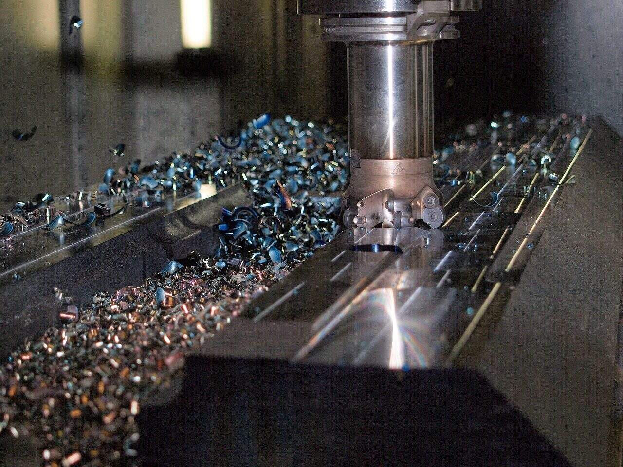
Le type de copeau produit au cours d'une opération n'est pas aléatoire ; c'est un indicateur direct des conditions de coupe. En examinant le copeau, un ingénieur compétent peut obtenir des informations sur l'efficacité du processus, l'état de l'outil et l'adéquation des paramètres sélectionnés. La façon dont le copeau se forme détermine sa forme, qui a des effets importants sur l'opération d'usinage. Différents matériaux et conditions de coupe produisent des types de copeaux distincts, chacun ayant ses propres caractéristiques et ce qu'il révèle du processus.
| Type de puce | Comment se forme-t-il ? | Matériaux typiques | Ce que cela signifie pour l'usinage |
| Puce continue | Déformation plastique lisse et continue dans la zone de cisaillement primaire. | Matériaux ductiles (par exemple, acier à faible teneur en carbone, aluminium) | Bon état de surface, efforts de coupe réguliers, mais peut poser des problèmes de manipulation (copeaux longs et filandreux). |
| Puce discontinue | Le matériau se brise en segments en raison d'une faible ductilité ou d'un frottement élevé. | Matériaux fragiles (par exemple, fonte) ou des vitesses de coupe très faibles. | Bonne capacité à briser les copeaux, mais peut conduire à des forces changeantes et à un moins bon état de surface. |
| Continu avec le bord de l'ouvrage (BUE) | Les couches de matériau de la pièce adhèrent et se soudent à la face de l'outil, puis se détachent. | Matériaux ductiles à des vitesses de coupe moyennes. | Protège l'arête de coupe mais se casse périodiquement, ce qui détériore l'état de surface et provoque l'usure. |
Analyse des forces en présence
Chaque opération de coupe de métal implique un système de forces agissant sur l'outil et la pièce à usiner. Il est essentiel de comprendre quantitativement ce système pour prévoir la consommation d'énergie, concevoir des montages solides, analyser la stabilité du processus et prévenir les défaillances de l'outil. Ces forces proviennent de l'énergie nécessaire au cisaillement du matériau dans la zone de cisaillement primaire et de l'énergie de frottement utilisée lorsque le copeau glisse sur la face de coupe de l'outil. La mesure et l'analyse de ces forces permettent de déterminer l'efficacité et la stabilité du processus de coupe.
Le système de la force de coupe
Le système de forces complexe peut être simplifié et décomposé en composantes perpendiculaires pour une analyse pratique. Les principales forces qui nous intéressent sont les suivantes :
- Force de coupe (Fc) : Il s'agit de la composante principale et généralement la plus importante de la force. Elle agit dans la direction de la vitesse de coupe. L'importance de la force de coupe, multipliée par la vitesse de coupe, détermine la puissance nécessaire pour effectuer la coupe. C'est le facteur principal dans le calcul de la consommation d'énergie de la machine-outil.
- Force de poussée (Ft) : Également appelée force d'avance, cette composante agit perpendiculairement à la vitesse de coupe, dans le sens de l'avance de l'outil. Bien qu'elle contribue moins à la consommation d'énergie, la force de poussée est essentielle pour la précision dimensionnelle. Des forces de poussée élevées peuvent entraîner la flexion de l'outil, de la pièce à usiner ou des composants de la machine, ce qui entraîne des erreurs dimensionnelles et des vibrations potentielles.
- Force résultante (R) : il s'agit de la somme vectorielle de la force de coupe et de la force de poussée. Elle représente la charge totale exercée sur l'outil de coupe et doit être gérée par le porte-outil, la broche et la structure de la machine.
Le diagramme du cercle des marchands
Le diagramme circulaire de Merchant est un outil graphique puissant pour analyser les relations entre les forces, les angles et le frottement dans la coupe orthogonale. Il nous permet de visualiser comment les changements d'un paramètre, comme l'angle de cisaillement, affectent l'ensemble du système de forces. Au lieu d'être un concept abstrait, il s'agit d'une méthode pratique pour comprendre la mécanique de la coupe.
Voici comment nous pouvons construire et interpréter le diagramme :
- Nous commençons par mesurer la force de coupe (Fc) et la force de poussée (Ft) à l'aide d'un dynamomètre. Ces deux forces sont représentées par des vecteurs perpendiculaires. Leur somme vectorielle nous donne la force résultante (R), qui forme le diamètre du cercle marchand.
- À partir de la pointe de l'outil, nous traçons une ligne représentant la face de coupe de l'outil à l'angle de coupe connu (α). Les composantes de la force agissant le long de cette face sont la force de frottement (F), qui s'oppose au mouvement du copeau, et la force normale (N), qui agit perpendiculairement à la face de coupe. La résultante (R) est la somme vectorielle de F et N.
- Ensuite, nous traçons une ligne représentant le plan de cisaillement à l'angle de cisaillement calculé (φ). Les composantes de la force agissant le long de ce plan sont la force de cisaillement (Fs), qui est la force nécessaire pour cisailler le matériau, et la force normale au plan de cisaillement (Fn). La résultante (R) est également la somme vectorielle de Fs et Fn.
L'élément clé de ce diagramme est sa capacité à montrer visuellement l'effet de l'angle de cisaillement. Pour une force résultante R donnée, si nous augmentons l'angle de cisaillement (φ), la corde représentant la force de cisaillement (Fs) devient plus courte. Cela prouve graphiquement qu'un angle de cisaillement plus grand réduit la force nécessaire à la formation du copeau, ce qui conduit à un processus de coupe plus efficace.
Génération et contrôle de la chaleur dans la coupe
La quasi-totalité de l'énergie utilisée dans les le découpage du métal est transformé en chaleur. La production et la gestion de cette énergie thermique sont parmi les aspects les plus critiques de l'économie mondiale. ingénierie des procédésLa température est souvent le principal facteur limitant la productivité et la durée de vie de l'outil. Les températures générées peuvent être extrêmement élevées, affectant grandement l'outil, le copeau et la surface de la pièce nouvellement usinée. Comprendre les sources de cette chaleur et sa distribution est fondamental pour contrôler le processus de coupe.
Sources primaires de chaleur
La chaleur intense de la coupe des métaux provient de trois sources distinctes :
- Zone de cisaillement primaire : il s'agit de la plus grande source de chaleur, représentant la majorité de l'énergie thermique totale. La chaleur est générée par la déformation plastique importante du matériau de la pièce lors de sa transformation en copeaux.
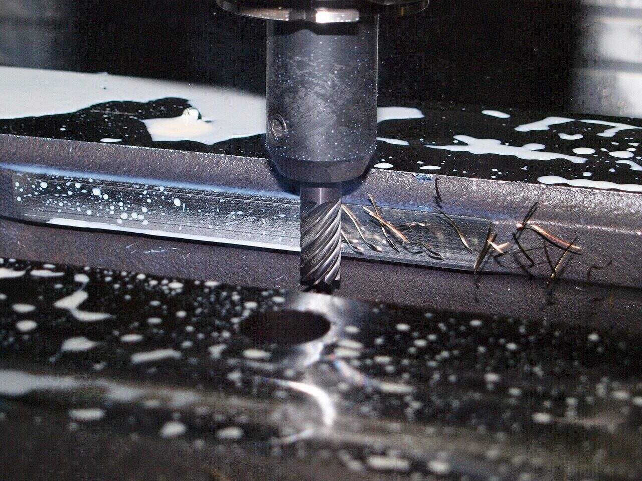
- Zone de cisaillement secondaire : il s'agit de la zone de frottement entre le copeau nouvellement formé et la face de coupe de l'outil. Lorsque le copeau chaud et fortement sollicité glisse à grande vitesse sur l'outil, il se produit un échauffement intense par frottement.
- Interface outil-pièce : Une troisième source de chaleur est la friction générée par le frottement du flanc (face de dépouille) de l'outil sur la surface nouvellement usinée de la pièce. Cet effet est particulièrement important lorsque l'outil est usé.
La température et ses effets
La température n'est pas uniformément répartie dans la zone de coupe. Les températures les plus élevées ne se trouvent généralement pas à l'extrémité de l'arête de coupe, mais légèrement en arrière de l'arête, sur la face de coupe, où la combinaison de la pression et de la vitesse de glissement est à son maximum. La taille de ces températures peut être étonnante. Par exemple, les températures de la zone de cisaillement peuvent dépasser 1000°C lors de l'usinage de superalliages à base de nickel, températures auxquelles les matériaux des outils commencent à perdre leurs propriétés fondamentales.
Cette chaleur excessive a plusieurs conséquences critiques et souvent néfastes :
- Il réduit la dureté et la résistance du matériau de l'outil de coupe, un phénomène connu sous le nom d'adoucissement thermique, ce qui le rend plus susceptible de s'user et de se déformer.
- Il accélère les réactions chimiques entre l'outil et le matériau de la pièce, ce qui entraîne une usure par diffusion, principal mode de défaillance à des vitesses de coupe élevées.
- Elle peut créer des contraintes thermiques résiduelles indésirables à la surface de la pièce, ce qui peut avoir un impact négatif sur la durée de vie et les performances du composant.
- Elle peut causer des dommages microstructuraux à la couche superficielle de la pièce, tels que des transformations de phase ou la création d'une "couche blanche" dure et cassante.
Mécanismes d'usure des outils et défaillance
Les outils de coupe ne durent pas éternellement. La combinaison de contraintes mécaniques extrêmes et de charges thermiques intenses conduit inévitablement à l'usure de l'outil et à sa défaillance. Comprendre comment et pourquoi les outils s'usent n'est pas seulement une question théorique ; c'est une nécessité pratique pour prévoir la durée de vie de l'outil, maintenir le contrôle du processus et garantir la qualité des pièces. L'usure des outils est le résultat direct des phénomènes physiques évoqués précédemment, à savoir les forces et la chaleur.
Types d'usure d'outils courants
L'usure des outils se présente sous plusieurs formes distinctes, chacune fournissant des indices sur le mécanisme de défaillance dominant :
- Usure du flanc : Il s'agit de l'usure abrasive qui se produit sur la face de dépouille (flanc) de l'outil en raison de la friction avec la surface usinée. Elle se présente sous la forme d'un "terrain d'usure" relativement uniforme et est souvent utilisée comme critère prévisible et fiable pour déterminer la fin de la durée de vie utile d'un outil.
- Usure par cratère : Il s'agit d'une dépression ou d'un "cratère" qui se forme sur la face de coupe de l'outil. Elle est causée par les températures et les pressions élevées du copeau qui glisse sur la face, ce qui favorise la diffusion chimique et l'abrasion. Elle est fréquente lors de l'usinage d'aciers à grande vitesse.
- Usure par entaille : Il s'agit d'une zone localisée d'usure accélérée qui se produit au niveau de la ligne de profondeur de coupe, là où l'arête de coupe interagit avec la surface d'origine de la pièce, souvent trempée ou oxydée.
- Ébréchure/fracture : Il s'agit d'une défaillance catastrophique au cours de laquelle un morceau de l'arête de coupe se détache. Elle est généralement causée par des charges mécaniques excessives, des chocs thermiques (changements rapides de température) ou l'usinage d'inclusions dures dans le matériau de la pièce.
La science derrière l'usure
Dans n'importe quel atelier d'usinage, vous verrez des opérateurs vérifier leurs outils. Ils ne se contentent pas de rechercher des dommages ; ils lisent une histoire écrite par la physique. Un bord arrondi et terne indique une abrasion, tandis qu'un cratère profond sur une plaquette en carbure utilisée pour la fabrication de pièces en acier est un signe d'usure. acier inoxydable indique "usure par diffusion". Voyons ce que signifient ces termes. Chaque modèle d'usure est régi par un ou plusieurs mécanismes scientifiques sous-jacents, qui sont activés par des conditions de coupe spécifiques.
| Mécanisme d'usure | Description | Conditions dominantes | Les moyens de la réduire |
| Abrasion | Les particules dures du matériau de la pièce (par exemple, les carbures) "poncent" mécaniquement le matériau de l'outil. | Faibles vitesses de coupe ; usinage de matériaux abrasifs. | Utiliser une qualité d'outil plus dure et plus résistante à l'usure (par exemple, céramique, CBN). |
| Adhésion | Micro-soudure entre le copeau et l'outil, suivie d'une fracture, arrachant le matériau de l'outil. Associé au BUE. | Vitesses faibles à moyennes ; grande affinité entre les matériaux de l'outil et du travail. | Augmenter la vitesse de coupe, utiliser des revêtements efficaces (par exemple, TiN), améliorer la lubrification. |
| Diffusion | Les atomes du matériau de l'outil se déplacent dans le copeau (et vice-versa) en raison des températures élevées, ce qui affaiblit l'outil. | Vitesses de coupe élevées, en particulier lors de l'usinage acier et alliages de nickel. | Utiliser des matériaux d'outils chimiquement stables (céramiques, CBN) ou des revêtements avancés (par exemple, Al2O3). |
| Fatigue | Fissures causées par les contraintes mécaniques ou thermiques répétéesLes coupes interrompues, telles que le fraisage, sont fréquentes. | Interruption des opérations de coupe (fraisage). | Utiliser une qualité d'outil plus résistante, optimiser la trajectoire de l'outil pour assurer une entrée/sortie en douceur. |
Intégrité de la surface : L'empreinte technique
L'objectif final de l'usinage des métaux n'est pas seulement d'atteindre une dimension spécifique, mais aussi de produire une surface présentant les performances fonctionnelles requises. L'intégrité de la surface est un terme général qui décrit la qualité et le caractère de la surface et de la couche de subsurface d'un composant usiné. Elle va bien au-delà de la simple apparence ou de la rugosité et inclut les propriétés mécaniques et métallurgiques qui déterminent les performances de la pièce dans son environnement de service. Les mécanismes de coupe créent directement une empreinte technique sur cette surface.
Définition de l'intégrité de la surface
L'intégrité de la surface est un concept à multiples facettes qui comprend plusieurs éléments clés :
- Finition/rugosité de la surface : Il s'agit de la topographie ou de la texture à échelle fine de la surface, généralement mesurée en Ra ou Rz. Il est principalement déterminé par la géométrie de l'outil et la vitesse d'avance.
- Modifications de la microstructure : La déformation et la chaleur intenses de la coupe peuvent modifier la structure du grain du matériau juste sous la surface. Il peut s'agir de déformation plastique, de transformations de phase ou de la formation d'une "couche blanche" très dure et cassante.
- Contraintes résiduelles : Il s'agit des contraintes qui restent bloquées dans la couche superficielle du matériau une fois que le processus de coupe est terminé et que toutes les charges externes ont été supprimées.
Comprendre les contraintes résiduelles
L'état des contraintes résiduelles dans un composant fini est un aspect critique, mais souvent négligé, de l'intégrité de la surface. Ces contraintes internes peuvent avoir un impact significatif sur la durée de vie en fatigue, la résistance à la corrosion et la stabilité dimensionnelle d'une pièce. Les contraintes résiduelles sont le résultat d'une compétition entre deux effets opposés :
- Effet mécanique : L'action de labourage et de brunissage du rayon du nez de l'outil de coupe déforme plastiquement la couche superficielle. Cette action tend à créer des contraintes résiduelles de compression, ce qui est généralement bénéfique car cela peut empêcher l'apparition et la propagation de fissures de fatigue.
- Effet thermique : L'échauffement intense et localisé de la surface par le processus de coupe, suivi d'un refroidissement rapide (trempe) par le matériau environnant et le liquide de refroidissement, tend à créer des contraintes résiduelles de traction. Les contraintes de traction sont néfastes car elles peuvent favoriser la formation de fissures et réduire la durée de vie en fatigue.
L'état de contrainte final est le résultat net de cette bataille. Des outils affûtés, des rayons de nez plus grands et des paramètres de coupe modérés tendent à favoriser l'effet mécanique, produisant des contraintes de compression bénéfiques. À l'inverse, des outils usés et une coupe agressive à haute température peuvent entraîner la prédominance de l'effet thermique, laissant derrière eux de dangereuses contraintes de traction dans le composant.
Contrôle de l'intégrité au moyen de paramètres
L'intégrité de la surface finale n'est pas un accident, c'est un résultat technique. En sélectionnant soigneusement les paramètres de coupe, nous pouvons contrôler les effets mécaniques et thermiques pour obtenir les caractéristiques de surface souhaitées.
| Paramètres | Effet sur la rugosité de la surface | Effet sur le stress résiduel |
| Vitesse de coupe | Améliore généralement (diminue la rugosité) jusqu'à un certain point, au-delà duquel l'usure de l'outil domine. | Tend à augmenter les contraintes de traction en raison d'effets thermiques plus importants. |
| Vitesse d'alimentation | Influence majeure : une alimentation plus élevée augmente directement la rugosité théorique. | Peut augmenter la contrainte de compression en raison d'une charge mécanique plus élevée, mais peut également causer davantage de dommages à la surface. |
| Rayon du nez de l'outil | Un rayon plus grand améliore généralement la finition en adoucissant les marques d'alimentation. | Un rayon plus grand augmente l'action de brunissage, ce qui favorise fortement les contraintes de compression bénéfiques. |
| Usure des outils | Les outils usés augmentent considérablement la rugosité et peuvent déchirer la surface. | Les outils usés augmentent les charges thermiques et mécaniques, ce qui entraîne souvent une évolution vers des contraintes de traction néfastes. |
Conclusion : Maîtriser les principes
Le voyage à travers la mécanique de la coupe des métaux révèle un système profondément lié. Le cisaillement initial détermine le type de copeau, qui à son tour influence les forces et la chaleur générées. Ces forces et ces charges thermiques entraînent les mécanismes d'usure de l'outil qui se développent au fil du temps. Enfin, l'effet combiné de l'action de l'outil, des forces, de la chaleur et de son état d'usure laisse une empreinte permanente sur la pièce sous la forme de l'intégrité de sa surface.
Une compréhension technique approfondie de ces principes est ce qui distingue le praticien de l'expert. Elle transforme l'usinage d'un art basé sur la sensation et l'expérience en une science basée sur des lois physiques prévisibles et contrôlables. En maîtrisant ces principes fondamentaux, les ingénieurs et les machinistes sont en mesure de diagnostiquer les problèmes, d'optimiser les processus pour une efficacité et une qualité maximales et, en fin de compte, de repousser les limites de la technologie de fabrication. Dans ce domaine, la formation continue n'est pas seulement une option, c'est la pierre angulaire de l'innovation et de l'excellence.
- Galvanisation - Wikipédia https://en.wikipedia.org/wiki/Electroplating
- Anodisation - Wikipédia https://en.wikipedia.org/wiki/Anodizing
- ScienceDirect Topics - Traitement électrochimique des surfaces https://www.sciencedirect.com/topics/materials-science/electrochemical-surface-treatment
- ASTM International - Normes de traitement de surface https://www.astm.org/
- Association pour la protection et la performance des matériaux (AMPP) https://ampp.org/
- ASM International - Ingénierie des surfaces https://www.asminternational.org/
- NIST - Science de la mesure des matériaux https://www.nist.gov/mml
- SpringerLink - Technologie des surfaces et des revêtements https://link.springer.com/journal/11998
- Materials Today - Ingénierie des surfaces https://www.materialstoday.com/
- SAE International - Normes de traitement de surface https://www.sae.org/
Produits associés
Solutions et groupe
- Composants de communication 5G
- Solutions de fixation sur mesure
- Fixations pour la communication 5G — Parcourir tous les articles
Articles associés
- Guide ultime de l'inspection dimensionnelle : Des principes de base aux méthodes modernes
- Tournage de précision avancé : Principes d'ingénierie pour des résultats parfaits
- Guide de l'expert : Les secrets de l'assemblage des équipements de télécommunications pour une performance parfaite du réseau
- Galvanisation à chaud : La science derrière la protection ultime de l'acier
- 5 Secrets du processus de traitement thermique : Les propriétés des métaux d'ingénierie révélées
- Guide essentiel de l'application des boulons à haute résistance : De la théorie à la pratique
- Guide essentiel des ébauches de forge : Du métal brut aux pièces de haute performance
- Guide ultime de l'ingénierie des connexions de tours : Des principes à la pratique