The Engineering Principles of Precision Turning: A Deep Technical Analysis
Introduction: Beyond the Lathe
Precision turning might look like a simple process: a spinning workpiece, a cutting tool, and material being removed. However, to achieve accuracy measured in tiny fractions of an inch and mirror-like surface finishes, we must look beyond just the lathe machine. True precision turning isn’t just an operation; it’s a complex, moving system of controlled interactions. It brings together physics, material science, machine movement, and control theory.
This article moves past the basic “what” and digs into the fundamental “why” and “how.” Our goal is to break down the core princípios de engenharia that control the outcome of every cut. We will explore the tiny events at the tool’s edge, the built-in properties of the material being shaped, the advanced engineering of the cutting tool, and the hidden forces that try to reduce accuracy. This is a journey into the science that transforms a raw piece of metal into a component of exact precision. We will treat precision turning as a complete system, understanding that mastery means controlling every variable within that system, from the shear zone of a metal chip to the heat stability of the machine tool.
The Fundamental Physics
To control a process, we must first understand its física básica. At its core, precision turning is a highly controlled breaking and shearing process. What happens in the tiny zone where the tool meets the workpiece determines the final quality of the part. By understanding these first principles, we can make smart, predictable adjustments to our settings.
The Shear Zone Explained
As the cutting tool engages the workpiece, it applies huge compressive stress on the material ahead of it. This material doesn’t simply “get cut”; it deforms plastically until it reaches its maximum shear strength. At this point, the material fails along a plane known as the primary shear zone, which extends from the tool tip to the free surface of the workpiece. This failure is what forms the chip. The nature of this chip tells us a great deal about the process.
- Continuous Chip: This is the ideal for most bendable materials like aluminum or low-carbon steel. A long, continuous ribbon flows smoothly up the tool face. It indicates a stable cutting process and generally results in a good surface finish.
- Discontinuous Chip: Common in brittle materials like ferro fundido or when cutting at very low speeds. The chip forms in small, broken segments. While it offers easy chip management, it can lead to a rougher surface.
- Serrated or Segmented Chip: A semi-continuous chip with a sawtooth-like appearance on the side that was not in contact with the tool. This is typical when machining difficult materials like titanium or nickel alloys at high speeds.
- Built-Up Edge (BUE): This is an unwanted phenomenon where small particles of the workpiece material pressure-weld themselves to the cutting edge. As the BUE grows and then breaks off, it takes fragments of the tool with it and damages the newly machined surface, leading to poor finish and faster tool wear.
The Trinity of Parameters
The interaction within the shear zone is directly controlled by three primary inputs. We call them the trinity of cutting parameters because their balance is critical to success.
- Cutting Speed (Vc): This is the relative velocity between the workpiece surface and the cutting tool, typically measured in surface feet per minute (SFM) or meters per minute (m/min). It is the most significant factor influencing temperature at the cutting zone and has a profound effect on tool life and surface finish.
- Feed Rate (f): This is the distance the tool advances along the axis of the workpiece for every single revolution. It is measured in inches per revolution (IPR) or millimeters per revolution (mm/rev). Feed rate is the primary determinant of the theoretical surface roughness.
- Depth of Cut (ap): This is the thickness of the material being removed from the workpiece radius in a single pass. It directly influences cutting forces, power consumption, and the Material Removal Rate (MRR).
These three parameters are closely linked. Increasing one often requires adjusting another to maintain process stability. For example, a higher feed rate will increase MRR but may worsen surface finish, requiring an adjustment in cutting speed or tool nose radius to compensate.
Analyzing Cutting Forces
Every cutting action generates a reaction force, which can be broken down into three perpendicular components. Understanding these forces provides a diagnostic window into the cutting process.
- Tangential Force (Fc): The largest of the three, acting downward on the tool. It is the primary force determining the power required for the cut.
- Feed Force (Ff): Acts parallel to the workpiece axis, opposing the tool’s feed motion.
- Radial Force (Fr): Acts perpendicular to the workpiece, pushing the tool away from the centerline.
High cutting forces are a direct enemy of precision. The radial force, in particular, can cause the workpiece to bend (especially on long, slender parts) or the tool to push away, resulting in dimensional inaccuracies like taper. For context, turning 6061-T6 aluminum might generate tangential forces in the range of 400-800 N/mm², while turning hardened 4140 steel under similar conditions could easily exceed 2500 N/mm², drastically increasing the risk of deflection. Monitoring these forces is key to diagnosing and preventing errors.
A ciência dos materiais
A cutting tool and a set of parameters that work perfectly for aluminum will fail catastrophically on titanium. The reason lies in the built-in properties of the workpiece material. Precision turning requires us to think like metallurgists, understanding how a material’s internal structure dictates its response to the extreme stresses and temperatures of machining.
Principais propriedades do material
We can predict a material’s behavior by analyzing a few key properties. These characteristics determine everything from chip formation to tool life.
- Hardness & Strength: Hardness is a material’s resistance to localized plastic deformation, such as scratching or indentation. Strength is its ability to withstand an applied load without failure or plastic deformation. Harder, stronger materials require greater cutting forces, generate more heat, and cause more rapid tool wear.
- Ductility: This is a measure of a material’s ability to undergo significant plastic deformation before breaking. Highly ductile materials, like copper or mild steel, tend to form long, continuous chips that can be difficult to manage. Brittle materials, like grey cast iron, have low ductility and form easily managed, discontinuous chips.
- Thermal Conductivity: This property describes how efficiently a material can conduct heat away from the cutting zone. Materials with low thermal conductivity, such as titanium and aço inoxidável, concentrate intense heat at the tool’s cutting edge, leading to rapid thermal wear and potential tool failure. Aluminum, with its high thermal conductivity, dissipates heat effectively, making it much easier to machine.
- Work Hardening: Also known as strain hardening, this is the tendency of a material to become harder and stronger as it is plastically deformed. Materials with a high work hardening rate, like austenitic stainless steels (e.g., 304, 316), become significantly harder in the zone being cut. This means the tool is continuously engaging a surface that is harder than the parent material, leading to accelerated wear and increased cutting forces.
The Machinability Index
To provide a general guideline, engineers developed the machinability index or machinability rating. This is a comparative score that rates a material’s ease of machining against a standard benchmark. The most common benchmark is AISI 1212 steel, which is assigned a rating of 100%. A material with a rating of 50% is considered twice as difficult to machine as 1212 steel, while a material like free-machining brass might have a rating over 300%.
cURL Too many subrequests. tratamento térmicocURL Too many subrequests.
cURL Too many subrequests.
cURL Too many subrequests.
| Material | cURL Too many subrequests. | cURL Too many subrequests. | cURL Too many subrequests. | cURL Too many subrequests. |
| cURL Too many subrequests. | cURL Too many subrequests. | 800 – 2000 | 0.008 – 0.020 | cURL Too many subrequests. |
| Baixa Aço carbono 1018 | cURL Too many subrequests. | 600 – 1200 | 0.010 – 0.025 | cURL Too many subrequests. |
| cURL Too many subrequests. | cURL Too many subrequests. | 250 – 500 | 0.006 – 0.015 | cURL Too many subrequests. |
| cURL Too many subrequests. | cURL Too many subrequests. | 100 – 200 | 0.005 – 0.012 | cURL Too many subrequests. |
cURL Too many subrequests.
cURL Too many subrequests.
cURL Too many subrequests.
cURL Too many subrequests.
- cURL Too many subrequests.
- cURL Too many subrequests.
- cURL Too many subrequests.
- cURL Too many subrequests.
- cURL Too many subrequests.
- cURL Too many subrequests.
cURL Too many subrequests.
cURL Too many subrequests.
- cURL Too many subrequests.
- cURL Too many subrequests.
- cURL Too many subrequests.
- cURL Too many subrequests.
- cURL Too many subrequests.
cURL Too many subrequests.
cURL Too many subrequests.
| Atributo | cURL Too many subrequests. | cURL Too many subrequests. | Diamante Policristalino (PCD) |
| cURL Too many subrequests. | cURL Too many subrequests. | Synthetic CBN crystals sintered onto a carbide substrate. | Synthetic diamond particles sintered together, often on a carbide substrate. |
| Hardness (Knoop) | ~1800 – 2400 | ~4500 – 5000 | ~6500 – 8000 |
| Aplicativo | General purpose machining of steels, stainless steels, cast irons, and non-ferrous alloys. | Hard turning of ferrous materials (>45 HRC), such as hardened steels and chilled cast irons. | High-speed finishing of non-ferrous and non-metallic materials (aluminum, brass, composites, carbon fiber). |
| Prós | Excellent balance of hardness and toughness. Versatile and cost-effective. Wide variety of geometries and grades. | Extreme hot hardness. Chemically stable with ferrous materials. Allows for replacement of grinding operations. | The ultimate in hardness and wear resistance. Can achieve exceptional surface finishes. Excellent thermal conductivity. |
| Contras | Lower hot hardness compared to ceramics/CBN. Limited speeds in very hard materials. | Brittle and sensitive to interrupted cuts. High cost. Not suitable for soft materials. | Very brittle. High cost. Chemically reactive with ferrous materials at high temperatures, making it unsuitable for steel. |
Enemies of Precision
In a perfect world, a rigid machine with a perfect tool would produce a perfect part. In reality, we operate in a world filled with “unseen enemies”—subtle forces and phenomena that constantly work to degrade accuracy. Identifying and reducing these error sources is the hallmark of a true precision expert.
Battle Against Heat
Heat is the primary enemy in precision turning. The energy from plastic deformation and friction shows up as intense heat, concentrated in a tiny area. This heat causes thermal expansion in the workpiece, the tool, and even the machine tool structure itself. A part measured at 200°C will be a different size when it cools to an ambient temperature of 20°C. This thermal growth is a direct source of dimensional error.
Mitigation is centered on thermal management and stability.
- Coolant/Lubricant Strategy: The most direct approach is the application of cutting fluid.
- Flood Cooling: The traditional method of showering the cutting zone with a low-pressure, high-volume flow of coolant. It is effective at bulk heat removal and chip flushing.
- High-Pressure Coolant (HPC): Delivers a focused, high-velocity jet of coolant directly at the cutting edge. This can break the vapor barrier that forms at high temperatures, providing more effective cooling and also aiding in chip control by breaking chips into manageable sizes.
- Minimum Quantity Lubrication (MQL): Also known as near-dry machining, this method delivers a fine aerosol of oil in an air stream. It focuses on lubrication rather than cooling, reducing friction and thus the amount of heat generated in the first place.
- Machine Warm-up Cycles: Running a machine’s spindle and axes before starting critical work helps bring the entire structure to a stable operating temperature, minimizing thermal drift during the machining process.
Taming Instability and Chatter
Chatter, or self-excited vibration, is a destructive phenomenon that can ruin a part in seconds. It occurs when the cutting force causes the tool or workpiece to deflect, which then changes the chip thickness. This change in chip thickness alters the cutting force, creating a feedback loop that results in violent vibration. The result is a terrible surface finish with characteristic wave patterns and, often, catastrophic tool failure.
Common causes include:
- Lack of system rigidity (machine, tool holder, workpiece).
- Excessive tool overhang.
- Incorrect cutting parameters that excite a natural frequency of the system.
- Dull or incorrect tool geometry.
Mitigation involves increasing system stiffness (shorter tools, better workholding) and adjusting cutting parameters. Advanced engineering utilizes tools like stability lobe diagrams, which are plots of axial depth of cut versus spindle speed. These diagrams map out the speed-parameter combinations that are dynamically stable (chatter-free) and those that are unstable, allowing engineers to scientifically select chatter-free cutting conditions.
The Foundation of Accuracy
Ultimately, the precision potential of any turning operation is limited by the machine tool itself. No amount of process optimization can overcome the inherent kinematic errors of the machine. These are the foundational errors built into the machine’s structure and motion systems.
- Machine Base Rigidity: A massive, well-damped machine base (often made of polymer concrete or cast iron) absorbs vibrations and provides a stable platform.
- Guideway Straightness and Spindle Runout: The ways that guide the machine’s axes must be perfectly straight and parallel. The spindle must rotate with minimal radial or axial deviation (runout). Any error in these components will be directly copied onto the workpiece.
- Control System and Servo Performance: The CNC control’s ability to precisely command and verify the position of the cutting tool, and the servo motors’ ability to execute those commands without overshoot or lag, are critical for contouring accuracy and positional repeatability.
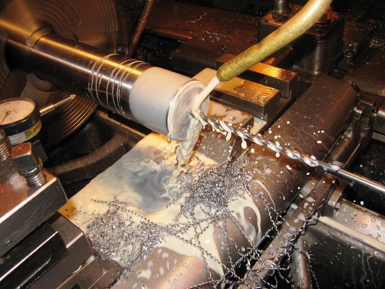
Table 3: Diagnostic Guide
The ability to diagnose a problem from the evidence left on a part is a critical skill. This table serves as a quick-reference troubleshooting guide for common precision turning errors.
| Symptom / Error | cURL Too many subrequests. | cURL Too many subrequests. |
| cURL Too many subrequests. | cURL Too many subrequests. | cURL Too many subrequests. |
| cURL Too many subrequests. | cURL Too many subrequests. | cURL Too many subrequests. |
| cURL Too many subrequests. | cURL Too many subrequests. | cURL Too many subrequests. |
| cURL Too many subrequests. | cURL Too many subrequests. | cURL Too many subrequests. |
cURL Too many subrequests.
cURL Too many subrequests.
cURL Too many subrequests.
cURL Too many subrequests. matéria-prima cURL Too many subrequests.
- cURL Too many subrequests. https://www.sme.org/technologies/machining-metal-cutting/
- cURL Too many subrequests. https://www.engineeringtoolbox.com/
- cURL Too many subrequests. https://www.machinedesign.com/
- cURL Too many subrequests. https://www.asme.org/
- cURL Too many subrequests. https://en.wikipedia.org/wiki/Machining
- cURL Too many subrequests. https://www.thomasnet.com/products/cnc-turning-services-73131200-1.html
- cURL Too many subrequests. https://www.iqsdirectory.com/articles/machine-shop/lathe.html
- cURL Too many subrequests. https://www.asme.org/topics-resources/content/manufacturing-science-engineering
- cURL Too many subrequests. https://www.bls.gov/ooh/architecture-and-engineering/mechanical-engineers.htm
- cURL Too many subrequests. https://ocw.mit.edu/courses/mechanical-engineering/
Produtos Relacionados
Soluções e Agrupamentos
- Componentes de comunicação 5G
- Soluções de fixação personalizadas
- Fixadores para Comunicação 5G — Veja todos os artigos
Artigos Relacionados
- Guia essencial para instalação de parafusos de engenharia: Dominando a tensão perfeita
- Guia definitivo: Parafusos de aço-liga Seleção de matéria-prima para resistência máxima
- Guia essencial para forjar peças em bruto: From Raw Metal to High-Performance Parts (Do metal bruto às peças de alto desempenho)
- The Ultimate Guide to Cold Heading Steel (Guia definitivo para laminação a frio de aço): A ciência por trás da conformação de metais
- Guia definitivo de fixação de gabinetes: Princípios de engenharia para construtores profissionais
- Guia essencial para aplicação de parafusos de alta resistência: Da teoria à prática
- Guia essencial para teste de torque: Da física básica aos métodos profissionais
- Guia do especialista: Segredos da instalação da estação rádio-base para redes móveis perfeitas