The Science of Shine: Understanding How Electroplating Works
Introdução
From the shiny chrome on a classic car bumper to the gold coating on smartphone parts, electroplated surfaces are everywhere in our modern world. These coatings protect against rust, reduce wear, improve electrical connections, and make things look better. Many people think electroplating is just “putting one metal on top of another metal,” but this simple view misses the real story. The process is actually a smart use of science principles. This article goes beyond basic explanations to give you a clear technical look at the chemistry that makes electroplating work. At its heart, electroplating is a carefully controlled process that uses electrochemistry, follows Faraday’s Laws, and depends on understanding how electrode reactions work and complex solution chemistry.
The Electrochemical Cell
The Four Essential Parts
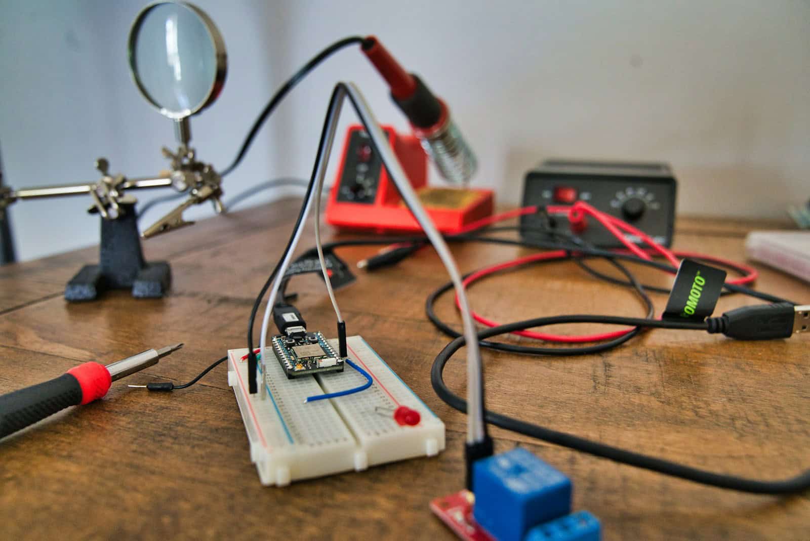
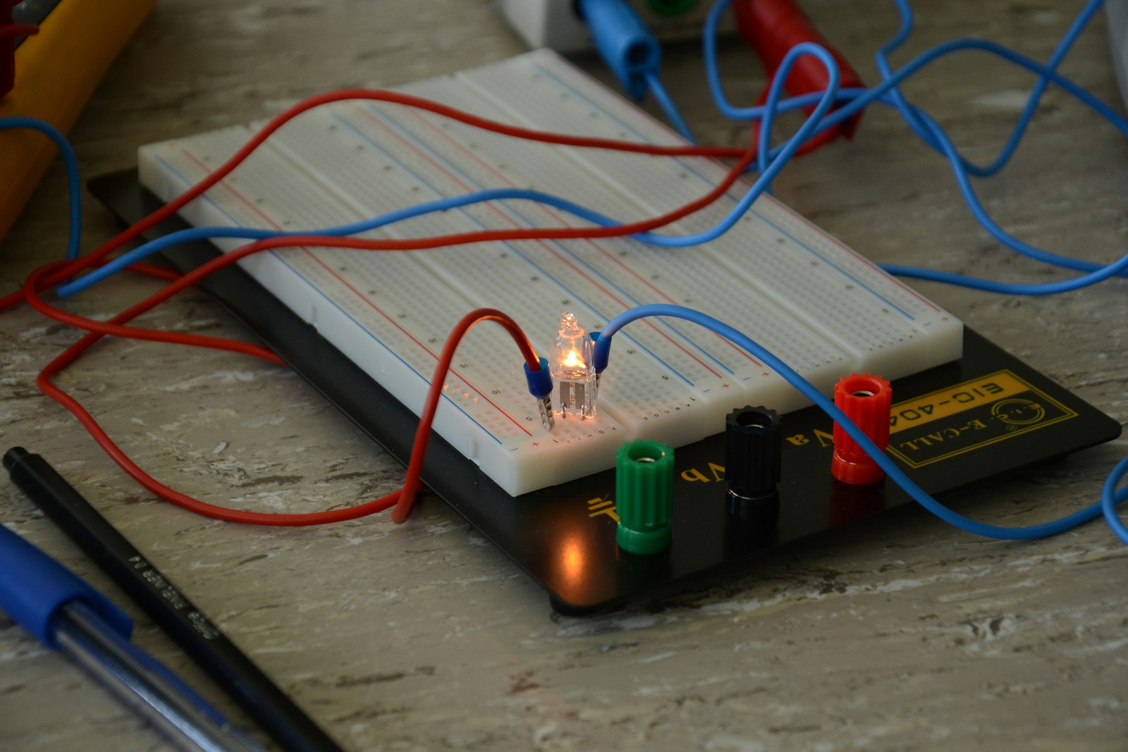
To understand electroplating, we need to break down the system into its main parts. Every electroplating setup, whether big or small, simple or complex, is an electrochemical cell made of four componentes essenciais. These parts work together in a connected circuit to force a chemical reaction that wouldn’t happen naturally, resulting in a metal layer being deposited onto an object. Understanding what each part does is the foundation for mastering the entire process.
- The Anode (+): The anode is the positive electrode in the cell. How it works depends on whether it dissolves or stays solid. A dissolving anode, usually made of the same metal being plated (like a pure nickel bar in a nickel plating bath), does two jobs. It completes the electrical circuit and adds metal ions to the solution as it dissolves. This keeps the metal concentration in the bath steady. On the other hand, a non-dissolving anode, often made of materials like platinum-coated titanium or graphite, doesn’t dissolve. Its only job is to complete the circuit. In this case, the metal ions for plating must be added by periodically putting metal salts into the bath. The main reaction at the anode is always oxidation—the loss of electrons.
- The Cathode (-): The cathode is the negative electrode in the cell. This is the workpiece, the base material, or the part that will be plated. It connects to the negative terminal of the power supply. The surface of the cathode is where the desired reaction, metal deposition, happens. Positively charged metal ions moving through the solution are attracted to the negatively charged cathode. When they reach the surface, these ions gain electrons in a process called reduction, changing them from dissolved ions back into solid metal atoms. These atoms build up layer by layer, forming the plated coating.
- The Electrolyte (The Bath): The electrolyte, commonly called the plating bath, is the chemical solution that fills the tank. It is a highly complex and carefully balanced chemical mixture. Its most basic role is to provide a conductive path for ionic current to flow between the anode and the cathode. It contains dissolved metal salts (like nickel sulfate, copper cyanide) that provide the source of metal ions to be deposited. Beyond these primary components, the electrolyte contains many other chemicals, which we will explore later, that control conductivity, pH, and the final properties of the deposit.
- The DC Power Source (The Rectifier): Electroplating is a process that needs energy to work; it requires an external energy source to proceed. This is provided by a direct current (DC) power source, known in the industry as a rectifier. The rectifier acts as an electron pump. It pulls electrons away from the anode (oxidation) and pushes them into the cathode (reduction), creating the voltage difference that drives the entire system. The voltage and current supplied by the rectifier are critical process controls that directly affect the rate of plating and the quality of the final coating.
Faraday’s Laws of Electrolysis
From Electric Charge to Coating Thickness
Electroplating is a measurable science, and its predictability comes from the work of Michael Faraday. Faraday’s Laws of Electrolysis provide the mathematical foundation for calculating the amount of metal that will be deposited under a given set of electrical conditions.
Faraday’s First Law of Electrolysis states that the mass of a substance deposited at an electrode is directly proportional to the quantity of electric charge passed through the cell. This relationship is expressed by the fundamental equation of electroplating:
m = (I * t * M) / (n * F)
Understanding each variable is key to using this formula effectively:
- m: The theoretical mass of the metal deposited, typically in grams (g).
- I: The electric current applied, measured in Amperes (A). One Ampere is a flow of one Coulomb of charge per second.
- t: The duration of the plating process, measured in seconds (s).
- M: The molar mass of the metal being deposited, in grams per mole (g/mol). This is a constant for each element (like ~63.5 g/mol for Copper, ~58.7 g/mol for Nickel).
- n: The valence number, or the number of electrons required to reduce one metal ion to its solid form. For example, for Cu²⁺ from a copper sulfate bath, n=2. For Ag⁺ from a silver nitrate bath, n=1.
- F: The Faraday constant, which is the total electric charge contained in one mole of electrons. Its value is approximately 96,485 Coulombs per mole (C/mol).
Let’s consider a practical example: calculating the mass of copper deposited from a copper sulfate (CuSO₄) solution. In this solution, copper exists as Cu²⁺ ions, so n=2. If we plate a part at a constant current of 10 Amperes for 30 minutes (1800 seconds):
- Calculate total charge (Q): Q = I * t = 10 A * 1800 s = 18,000 Coulombs.
- Apply the full formula: m = (10 A * 1800 s * 63.5 g/mol) / (2 * 96,485 C/mol)
- m = 1,143,000 / 192,970 ≈ 5.92 grams of copper.
This calculation allows engineers to precisely predict coating thickness and material consumption.
The Concept of Current Efficiency
In a perfect world, every electron supplied by the rectifier would be used to reduce a metal ion. However, real-world plating baths are not 100% efficient. Competing electrochemical reactions can occur at the cathode, using up some of the current. The most common side reaction, especially in water-based acidic solutions, is the reduction of hydrogen ions or water to produce hydrogen gas (2H⁺ + 2e⁻ → H₂).
This diversion of current means the actual mass of metal deposited is less than the theoretical mass calculated by Faraday’s Law. This reality is accounted for by the concept of Current Efficiency (CE), expressed as a percentage.
CE (%) = (Actual mass deposited / Theoretical mass deposited) * 100
The practical formula for calculating the real-world yield becomes:
Actual mass = m (from Faraday’s Law) * CE
A typical bright nickel bath might operate at 95-97% current efficiency, while a chromium plating bath can have a notoriously low CE of only 15-25%, with the majority of the current going toward hydrogen evolution. Understanding and monitoring current efficiency is critical for process control, as changes in CE can indicate problems with bath chemistry or operating parameters.
The Electrolyte Bath
Beyond Metal Salts
The plating bath is far more than just a simple solution of metal salts and water. Modern electrolytes are complex chemical mixtures designed to produce deposits with specific properties like brightness, smoothness, and internal stress. The performance of a plating line depends just as much on its chemistry as it does on its electrical systems. The main components include:
- Metal Salts: This is the primary source of the metal ions for deposition. The choice of salt (like sulfate, chloride, sulfamate) can influence the conductivity of the bath and the properties of the deposit.
- Conducting Salts: These are added to increase the electrical conductivity of the solution. A more conductive bath requires a lower voltage to achieve the desired current density, making the process more energy-efficient. Sulfuric acid in a copper bath or sodium chloride in a nickel bath are common examples.
- pH Buffers: The pH of the electrolyte is a critical parameter. Changes can affect current efficiency, deposit appearance, and bath stability. Buffering agents, such as boric acid in a Watts nickel bath, are added to resist changes in pH that naturally occur during plating.
- Additives: This is where much of the specialized science of electroplating lies. These are typically organic or inorganic compounds added in very small concentrations (parts per million) that have a huge impact on the final deposit. They are the “secret ingredient” that transforms a dull, rough deposit into a smooth, brilliant, and functional coating.
Table 1: Understanding Plating Additives
The function of additives is best understood by categorizing them. The following table breaks down the main classes of additives and explains their specific roles in improving the electroplated layer.
| Additive Type | Primary Function | Example(s) |
| Carriers / Wetting Agents | Reduce the surface tension of the electrolyte, preventing gas bubbles (like hydrogen) from sticking to the cathode and causing pitting. | Surfactants, sodium lauryl sulfate |
| Brighteners | Refine the crystal grain structure of the deposit down to a microscopic level, resulting in a mirror-like, brilliant finish. They work by selectively sticking onto active growth sites. | Organic sulfur compounds, aldehydes, coumarin |
| Levelers | Promote the filling of microscopic scratches and valleys on the substrate surface faster than deposition occurs on peaks, resulting in a smoother, more level deposit. | Dyes, high molecular weight polymers, ethylene cyanohydrin |
| Stress Reducers | Counteract the internal tensile or compressive stress that builds up within the deposit as it forms. This prevents the coating from becoming brittle, cracking, or peeling. | Saccharin (for Nickel plating), naphthalenesulfonic acids |
The Electrode-Electrolyte Interface
Double Layer and Overpotential
The most critical action in electroplating occurs in a region of extremely small thickness at the interface between the cathode surface and the electrolyte. When the cathode is immersed in the solution and a negative potential is applied, a structured region known as the Electrical Double Layer forms. This layer consists of an ordered arrangement of ions and solvent molecules. It can be visualized as a microscopic capacitor, with one plate being the charged surface of the electrode and the other being a layer of oppositely charged ions (cations) from the solution.
For a metal ion to be successfully deposited, it must travel through this double layer and accept electrons from the cathode surface. This process is not instantaneous and faces several kinetic barriers. To overcome these barriers and drive the reaction at a practical rate, an extra voltage must be applied beyond the theoretical equilibrium potential. This “extra voltage” is a crucial concept known as Overpotential (η). Overpotential is the difference between the actual applied potential and the thermodynamic equilibrium potential. It is the driving force for the reaction and can be broken down into two main components:
- Activation Overpotential: This is the energy required to overcome the activation energy barrier of the electron transfer step itself. It is the energy needed to get the ion and electron to actually “react.”
- Concentration Overpotential: This arises when the deposition rate is so high that the metal ions in the immediate vicinity of the cathode are used up faster than they can be replaced from the bulk solution by diffusion and migration. The power supply must then provide extra voltage to attract ions from further away, leading to a rise in overpotential.

Current Density and Crystals
The relationship between current density and overpotential is the fundamental principle that allows us to control the physical properties of the deposit, such as its grain structure and brightness. Current density is the amount of current per unit of surface area, typically measured in Amperes per square decimeter (A/dm²) or Amperes per square foot (ASF).
When an electroplater changes the current density, they are directly changing the overpotential at the cathode surface. This, in turn, determines the mechanism of crystal formation:
- At Low Current Density: The overpotential is low. This condition provides just enough energy to overcome the activation barrier for ions to deposit onto existing, energetically favorable crystal lattice sites. The process favors the growth of existing crystals rather than the formation of new ones. This results in a deposit with a large, coarse, and often columnar grain structure. Such deposits are typically soft, dull in appearance, and have low tensile strength.
- At High Current Density: The overpotential is significantly increased. This high-energy condition makes it possible to overcome the larger energy barrier required to form a brand new crystal nucleus on the substrate surface. The rate of new crystal nucleation begins to outpace the rate of existing crystal growth. This abundant creation of new nuclei leads to a deposit composed of extremely small, tightly packed crystals. This fine-grained structure scatters light differently, resulting in a harder, denser, and visually brighter deposit.
Therefore, the secret to a bright finish is not just the presence of brightener additives but the application of a sufficiently high current density to promote a high rate of nucleation. Brighteners and levelers work together with this principle, sticking onto the surface to further influence nucleation and growth at a microscopic level, refining the finish to a mirror-like shine.
Controle de parâmetros de processo
The Four Control Levers
Achieving a consistent, high-quality plated finish requires the careful control and balancing of several interconnected process variables. An experienced plater understands how to manipulate these “levers” to keep the process within its optimal operating window and to influence the properties of the final deposit.
- Current Density: As discussed, this is the primary driver of deposition rate and grain structure. It is the most direct control over the plating process. Operators use tools like a Hull Cell—a miniature plating tank with an angled cathode—to study the effects of a wide range of current densities on the deposit’s appearance in a single test. This helps them determine the optimal current density range for a given bath chemistry.
- Temperature: The temperature of the electrolyte affects nearly every aspect of the process. Higher temperatures increase the conductivity of the solution, improve the diffusion rate of ions (reducing concentration overpotential), and can increase current efficiency. However, there are trade-offs. Excessively high temperatures can cause additives to break down, increase internal stress, or lead to coarser grain structures. Each plating bath has an optimal temperature range that balances these factors.
- pH: Maintaining the pH of the bath within a narrow, specified range is critical. If the pH is too low (too acidic), it can lead to excessive hydrogen evolution, lowering current efficiency and potentially causing hydrogen embrittlement in the substrate. If the pH is too high (too alkaline), metal hydroxides can precipitate out of the solution, creating rough deposits and depleting the bath of metal.
- Agitation: Solution movement is essential for high-quality plating, especially at higher current densities. Agitation, which can be achieved through air sparging, mechanical stirring, or cathode rod movement, serves a critical function: it replenishes the depleted layer of metal ions at the cathode surface. This action reduces concentration overpotential, allowing for higher plating speeds without burning and ensuring a more uniform coating thickness across the part.
Table 2: Parameter-Property Matrix
The interaction between these parameters is complex. A change in one variable often requires an adjustment in another. The following matrix provides a quick-reference guide to the general cause-and-effect relationships between process parameters and key deposit properties.
| Parameter Change | Deposition Rate | Grain Size | Brightness | Estresse interno | Throwing Power |
| ↑ Current Density | Increases | Decreases (finer) | Increases (to a point) | Increases | Decreases |
| ↑ Temperature | Increases | Increases (coarser) | Decreases | Varies (often decreases) | Increases |
| ↑ Agitation | Increases | Increases (coarser) | Decreases | Decreases | Decreases |
| ↑ Metal Conc. | Increases | Increases (coarser) | Decreases | Decreases | Increases |
*Note: “Throwing Power” refers to the ability of a plating bath to produce a relatively uniform coating thickness on an irregularly shaped object.*
Troubleshooting Plating Defects
From Lab to Production
The true test of an electroplater’s expertise lies in their ability to diagnose and solve problems on the production line. A visual defect on a plated part is a symptom of an underlying issue in the electrochemical system. A systematic approach, grounded in the technical principles discussed, is essential for effective troubleshooting. In our experience, linking the visual evidence to a potential root cause in the bath chemistry or process parameters is the fastest path to a solution. When an operator sees blistering, for example, the first two things we check are surface preparation and the stress levels in the deposit, which are tied directly to additive balance and temperature. The following guide is designed to help engineers and technicians systematically diagnose common plating defects.
Table 3: An Engineer’s Guide to Plating Defects
This table provides a practical framework for identifying common issues, understanding their appearance, and tracing them back to their technical root causes.
| Defeito | Visual Appearance | Potential Root Cause(s) – Technical Analysis |
| Pitting | Small, circular depressions or pores in the deposit. | • Gas Pitting: Hydrogen bubbles sticking to the cathode surface, blocking deposition at that spot. This indicates insufficient wetting agent (high surface tension) or inadequate agitation.<br>• Solid Pitting: Particulate matter (dust, anode sludge) suspended in the bath co-deposits with the metal, then falls out, leaving a void. This points to poor filtration. |
| Burning | Dark, powdery, or non-adherent deposits, typically found on high current density areas like edges and corners. | • Excessive Current Density: The local current density is too high, causing the deposition rate to far exceed the rate of ion supply. This leads to extreme concentration overpotential, a sharp drop in current efficiency, and excessive hydrogen gas evolution, resulting in a poor quality, “burnt” deposit. |
| Blistering / Peeling | The plated layer lifts from the substrate in bubbles or sheets, indicating a failure of adhesion. | • Poor Adhesion: The most common cause is inadequate surface preparation. Residual oils, greases, or oxides on the substrate prevent a strong metallurgical bond from forming.<br>• High Internal Stress: The deposit is under high tensile stress, effectively pulling itself off the substrate. This is often caused by an improper additive balance (especially stress reducers), low operating temperature, or organic contamination. |
| Roughness | A sandy, abrasive, or gritty texture on the deposit surface instead of a smooth finish. | • Particulate Contamination: Anode sludge, dust from the air, or precipitated salts are suspended in the bath and become included in the deposit. This is a clear sign of insufficient or failed filtration.<br>• Excessive Brightener: A classic sign of organic contamination is when brightener breakdown products co-deposit, causing roughness. |
| Dullness | A lack of brightness or mirror-like quality in a deposit from a bath that is designed to be bright. | • Improper Current Density: The operating current density is outside the brightener’s effective range (either too low or too high).<br>• Brightener Depletion/Contamination: The brightener additives have been consumed through use and require replenishment, or they have been “poisoned” by metallic or organic contaminants in the bath, rendering them ineffective. |
 Mastering Surface Transformation
Conclusão
Our journey has taken us from the four fundamental pillars of the electrochemical cell to the complex interplay of process parameters and the microscopic events at the cathode surface. We have seen that the mass of metal deposited can be precisely calculated with Faraday’s Laws, and the final appearance and performance of that deposit are dictated by the intricate chemistry of the electrolyte and the kinetic realities of overpotential and current density. Finally, we have translated this theoretical knowledge into a practical, experience-based guide for diagnosing and solving real-world plating defects.
This deep dive reveals that consistent, high-quality electroplating is not an art form subject to mysterious forces. It is a rigorous science, firmly rooted in the principles of electrochemistry, materials science, and chemical engineering. By understanding and controlling these principles, we can transform the surface of a simple substrate into a high-performance coating engineered for a specific purpose. As demands for durability, functionality, and miniaturization continue to grow, the scientific mastery of this surface transformation process will only become more critical.
- Electroplating and Surface Finishing – NASF https://www.nasf.org/
- Metal Finishing and Electroplating Standards – ASTM International https://www.astm.org/products-services/standards-and-publications.html
- Electrochemistry and Plating – The Electrochemical Society https://www.electrochem.org/
- Surface Engineering and Coatings – ASM International https://www.asminternational.org/
- Electroplating Process Guide – Wikipedia https://en.wikipedia.org/wiki/Electroplating
- Metal Finishing Technologies – Products Finishing Magazine https://www.pfonline.com/
- Electroplating Chemistry – ScienceDirect https://www.sciencedirect.com/topics/chemistry/electroplating
- Corrosion and Surface Treatment – NIST https://www.nist.gov/
- Electroplating Services Directory – Thomasnet https://www.thomasnet.com/products/electroplating-services-95210500-1.html
- Surface Finishing Processes – Engineering ToolBox https://www.engineeringtoolbox.com/

 Mastering Surface Transformation