Guia Completo para Configuração de Torres de Celular: Construindo Redes Móveis Melhores
Por que acertar é importante
Configurar torres de celular corretamente é absolutamente essencial para criar uma rede móvel forte e confiável. É aqui que a ciência das ondas de rádio, a engenharia de edificações e a rede de computadores se unem em um único local físico. Apenas uma conexão solta, uma carga de peso mal calculada ou uma antena apontando na direção errada podem prejudicar o desempenho de uma rede avaliada em milhões de reais e afetar milhares de usuários de telefone. Este o guia vai além de manuais de instruções básicos para fornecer aos engenheiros e os gerentes de projeto o conhecimento técnico detalhado que eles precisam para a configuração da rede. Ele explica os principais princípios que tornam uma instalação bem-sucedida.
Vamos analisar cuidadosamente as partes técnicas necessárias para a instalação bem-sucedida da estação base, abordando:
- O partes básicas de uma moderna torre de celular
- As regras de ciência e engenharia para a escolha de locais.
- Uma comparação de diferentes métodos de configuração.
- Uma descrição passo a passo do processo de instalação física.
- Considerações especiais para configurações de rede 5G.
- A fase final de testes e aprovação.
Isso guia foi projetado como um documento técnico recurso, proporcionando a compreensão profunda necessária para concluir a instalação de estações base com a precisão exigida para o melhor desempenho da rede.

O que há dentro de uma torre de celular moderna
Uma torre de celular moderna não é uma peça única de equipamento, mas um sistema de peças especializadas trabalhando juntas. Compreender o que cada parte faz é importante para entender como elas dependem umas das outras durante a instalação. O sistema é dividido entre processamento no nível do solo e transmissão de rádio em altitudes elevadas.
Unidade de Banda Base (UBB)
A Unidade de Banda Base (UBB) é o cérebro do computador do site celular. Geralmente mantida em um edifício ou gabinete com controle de clima na parte inferior da torre ou na sala de equipamentos de um edifício, a UBB lida com todo o processamento de sinais digitais. Ela gerencia transferências de chamadas entre torres, agenda recursos de rede e se comunica com a rede principal. Converte voz e dados em sinais digitais para transmissão e processa sinais recebidos dos telefones dos usuários. A UBB se conecta às unidades de rádio por meio de cabos de fibra óptica de alta velocidade.
Unidade de Rádio Remota (RRU/RRH)
A Unidade de Rádio Remota (RRU), também chamada de Cabeça de Rádio Remota (RRH), é o “músculo” do sistema. Sua principal função é converter o sinal digital da BBU em um sinal de Rádio Frequência (RF) analógico, amplificá-lo ao nível de potência necessário e enviá-lo para a antena. Ela também recebe sinais RF fracos da antena, os amplifica e os converte em digital para transporte até a BBU. Colocar a RRU próxima à antena reduz o comprimento do cabo, o que diminui significativamente a perda de sinal e melhora a eficiência geral do sistema, especialmente na recepção de sinais fracos de telefones.
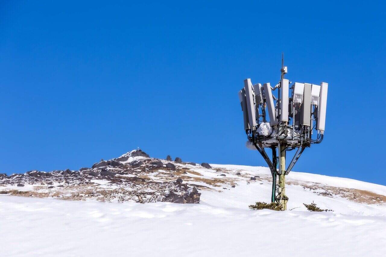
Sistema de Antenas
O sistema de antenas converte sinais elétricos em ondas de rádio e vice-versa. É a “boca e ouvidos” da rede. Antenas de painel são as mais comuns em redes celulares modernas, projetadas para criar setores de cobertura direcionais (tipicamente três setores de 120 graus por site). Conceitos-chave incluem polarização (usando múltiplas orientações para melhorar a força do sinal), azimute (apontamento horizontal) e inclinação mecânica/elétrica (apontamento vertical). Antenas avançadas suportam beamforming, que foca dinamicamente a energia de rádio em usuários específicos.
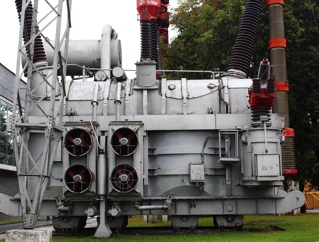
Sistemas de Energia e Resfriamento
O sistema de energia é a linha de vida. Torres de celular precisam de energia altamente confiável e limpa. Uma alimentação de energia AC é normalmente convertida para -48V DC, o padrão para equipamentos de telecomunicações. Um sistema de retificação realiza essa conversão e carrega um banco de baterias. Essa Fonte de Alimentação Ininterrupta (UPS) garante que o site continue funcionando durante quedas de energia por um tempo determinado. O resfriamento, por meio de unidades HVAC ou ventiladores de alta eficiência, é igualmente importante, pois a BBU e as RRUs geram calor significativo que deve ser removido para evitar falhas nos equipamentos.
Interface de Backhaul
O backhaul fornece a conexão do site com o mundo exterior — a rede principal da operadora e a internet. Cabo de fibra óptica de alta capacidade é preferido devido à sua enorme largura de banda, baixa latência e confiabilidade. Onde a fibra não está disponível ou custa muito, links de micro-ondas de alta frequência são utilizados, exigindo alinhamento preciso de linha de visão entre duas antenas parabólicas. A escolha da tecnologia de backhaul é uma decisão fundamental de projeto que determina a capacidade máxima de velocidade de dados do site.
| Tabela 1: Comparação das Classificações de Estações Base |
| Tipo |
| Macrocelular |
| Microcelular |
| Picocelular |
| Femtocelular |
A Ciência de Escolher Localizações
Escolher onde colocar uma torre de celular é a etapa de planejamento mais importante da instalação da estação base. É uma disciplina de engenharia baseada na física de como as ondas de rádio viajam. A melhor localização maximiza a cobertura e a capacidade, minimizando interferência e custo. Uma má escolha nunca pode ser totalmente corrigida pelo equipamento, por mais avançado que seja.
Análise de Ondas de Rádio
As ondas de rádio não viajam em linha reta e simples. A análise de ondas de rádio usa modelos matemáticos para prever como um sinal se comportará em um ambiente específico. Modelos como Okumura-Hata ou COST 231 são utilizados para planejamento de grandes células, levando em conta a densidade urbana e o tipo de terreno. Os fenômenos-chave que devem ser modelados incluem:
- Perda de Trajetória: A redução natural na força do sinal à medida que ele viaja pelo espaço.
- Sombras: Enfraquecimento do sinal causado por obstáculos grandes, como colinas ou edifícios.
- Multipath Fading: Interferência destrutiva e construtiva à medida que um sinal chega ao receptor por múltiplos caminhos (reflexões, contorno de obstáculos).
A frequência é um fator importante. Faixas de frequência mais baixas (como 700 MHz) percorrem distâncias maiores e penetram edifícios de forma mais eficaz do que faixas médias (como 2,5 GHz). Faixas de ondas milimétricas de alta frequência (como 28 GHz) têm alcance extremamente limitado e são facilmente bloqueadas por obstáculos.
Cálculo do Orçamento de Link
Um orçamento de link é uma contabilidade formal de todos os ganhos e perdas que um sinal de rádio sofre ao viajar do transmissor ao receptor. Seu objetivo é garantir que o sinal recebido seja forte o suficiente para manter uma conexão de qualidade. A fórmula simplificada é:
`Potência Recebida = Potência Transmitida + Ganhos – Perdas`
Cada termo representa um valor importante de engenharia:
- Potência Transmitida: A potência de saída do RRU.
- Ganhos: Principalmente ganho de antena, que concentra a energia de rádio em uma direção específica.
- Perdas: Uma combinação de Perda de Trajetória no Espaço Livre (FSPL), perdas de cabos e conectores, perdas por penetração (paredes, árvores) e uma margem de fading para compensar variações no sinal.
Uma margem de link positiva (potência recebida acima da sensibilidade do receptor) é necessária para uma conexão forte.
Prevenção de Interferência e PIM
Em uma rede densamente povoada, um site deve lidar com interferências de seus vizinhos. Interferência co-canal (de sites usando a mesma frequência) e interferência de canal adjacente (de sites em frequências próximas) devem ser gerenciadas por meio de planejamento cuidadoso de frequência e posicionamento de antenas.
Um problema mais oculto é o Intermodulação Passiva (PIM). PIM é uma forma de auto-interferência criada quando duas ou mais sinais de rádio fortes encontram não linearidades em componentes passivos como conectores, cabos ou até metal enferrujado próximo (cercas, telhados). Essas junções não lineares atuam como mixers, criando sinais novos e indesejados que podem cair diretamente na banda sensível de uplink, elevando o nível de ruído e prejudicando severamente o desempenho de chamadas e dados. A seleção do site deve evitar ativamente fontes potenciais de PIM.
Fatores Estruturais e Ambientais
O site escolhido deve ser capaz de suportar fisicamente o equipe. Uma análise estrutural é necessária para calcular a carga total, incluindo o peso de antenas, RRUs, suportes e cabos. Importante, essa análise também deve considerar a carga de vento, que exerce força significativa na torre ou estrutura do edifício, especialmente em grandes arranjos de antenas. Fatores ambientais também desempenham papel fundamental. O site deve ser avaliado quanto ao risco de raios, exigindo um plano de aterramento e proteção contra surtos robusto. Acesso durante o ano todo para veículos de manutenção, incluindo guindastes se necessário, é uma exigência logística que não pode ser negligenciada.
Análise dos Métodos de Instalação
Escolher o método de instalação adequado envolve uma série de trade-offs técnicos e financeiros. A melhor escolha depende do objetivo da rede, seja cobertura ampla, capacidade direcionada ou penetração em ambientes internos. Analisamos os três principais métodos com base em critérios de engenharia chave.
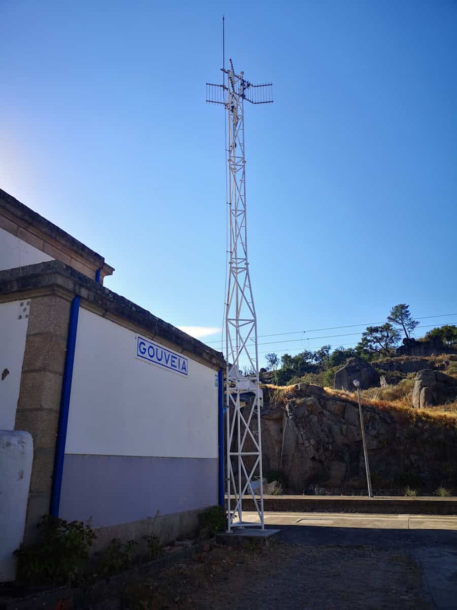
Instalação de Nova Torre
Uma nova instalação envolve a construção de uma nova torre (monopolo, autoportante ou com estai) em um terreno não desenvolvido.
- Desempenho de Rádio: Inigualável. Este método oferece a maior flexibilidade em altura e localização, permitindo que os engenheiros posicionem a antena no ponto ideal para máxima cobertura e mínima obstrução. É o padrão para implantações de células grandes em áreas rurais e suburbanas.
- Desafio estrutural: Significativo. Este é um grande civil projeto de engenhariaRequer levantamentos do solo para avaliar a estabilidade do terreno, uma grande fundação de concreto e um processo de construção da torre em várias etapas. Os prazos de implantação são os mais longos, frequentemente durando vários meses.
- Energia e Backhaul: Complexo e custoso. Energia elétrica de utilidade pública e backhaul de fibra muitas vezes precisam ser estendidos até o local, o que pode envolver escavações extensas, perfuração ou instalação de novos postes de utilidade, aumentando significativamente o custo e a complexidade da coordenação.
Instalação no telhado
Este método comum urbano e suburbano envolve montagem de antenas e equipamentos no telhado de um edifício existente.
- Desempenho do rádio: Muito bom, mas com limitações. Telhados oferecem altura excelente. No entanto, o desempenho pode ser prejudicado por obstruções de edifícios adjacentes mais altos ou por desordem de equipamentos existentes no telhado, como unidades de HVAC, o que pode causar reflexões e bloqueios de sinal. As estruturas metálicas em muitos telhados comerciais também são uma fonte de alto risco de PIM.
- Desafio estrutural: Crítico. Um engenheiro estrutural licenciado deve realizar uma análise detalhada para confirmar que o telhado da edificação pode suportar o peso combinado e a carga de vento da instalação proposta. Todos os orifícios no telhado para passagens de cabos e hardware de montagem devem ser cuidadosamente vedados e impermeabilizados para evitar vazamentos e manter a integridade do edifício.
- Energia e Backhaul: Geralmente mais acessível. Conectar-se à infraestrutura de energia e comunicações existente do edifício costuma ser mais fácil do que uma construção nova. No entanto, isso ainda pode exigir linhas de energia dedicadas de alta amperagem e trajetos complexos de fibra dentro do edifício, do telhado até o ponto de conexão de telecomunicações do prédio.
Célula Pequena / Mobiliário Urbano
Células pequenas são nós de baixa potência instalados em postes de iluminação, postes de utilidades ou nas laterais de edifícios para adicionar capacidade direcionada e preencher lacunas de cobertura.
- Desempenho de Rádio: Altamente localizado. A altura de instalação baixa e o nível de potência significam que a cobertura é limitada, muitas vezes a um quarteirão ou menos. O desempenho é altamente afetado por bloqueios de obstáculos ao nível da rua, como ônibus, árvores e até tráfego intenso de pedestres. Este método é para aumentar a capacidade, não para cobertura de área ampla.
- Desafio estrutural: Enganosamente complexo. Embora o equipamento seja menor e mais leve, a análise não é menos rigorosa. O poste de utilidade ou estrutura existente deve ser avaliado quanto à sua capacidade de suportar a carga adicional de vento. Aparência e conformidade com as leis de zoneamento locais e regulamentos de direito de passagem público são obstáculos importantes para o projeto.
- Energia e Backhaul: Frequentemente o maior desafio. Encontrar uma fonte de energia viável pode envolver negociações complexas para acessar o circuito de energia de um poste de iluminação pública. Garantir uma conexão de backhaul de fibra até um poste de utilidade no meio de uma quadra é uma tarefa logística e financeira significativa, às vezes custando mais do que o próprio equipamento de rádio.
Processo de instalação detalhado
A instalação física é uma sequência de ações precisas onde seguir as especificações técnicas é extremamente importante. Um erro em qualquer etapa pode comprometer a integridade de todo o sistema. Este processo é uma arte guiada por desenhos técnicos e melhores práticas.
1. Preparação do Site e Segurança
Antes de desembalar qualquer equipamento, o site deve ser preparado. Isso começa com o estabelecimento de uma zona de trabalho segura, usando cones, fita e sinais para controlar o acesso, especialmente se operações de levantamento estiverem planejadas. Todos os componentes entregues devem ser cuidadosamente verificados em relação à Lista de Materiais (BOM) e inspecionados quanto a danos durante o transporte. Uma avaliação final de risco no local é realizada para identificar quaisquer novos perigos ou riscos previamente não previstos.
2. Montagem Estrutural e de Suporte
Esta etapa envolve a montagem do hardware de suporte da antena, seja ele suportes de torre ou plataformas de cobertura no telhado, de acordo com os desenhos de engenharia estrutural. Este é um passo crítico de segurança. Todo hardware deve ser apertado de acordo com as especificações exatas do fabricante para evitar afrouxamento devido à vibração induzida pelo vento ao longo do tempo. Um detalhe importante, mas frequentemente negligenciado, é preparar todos os pontos de aterramento e ligação. Isso envolve remover tinta ou ferrugem para criar uma conexão metálica a metálica limpa e aplicar um composto anticorrosivo antes da montagem final para garantir uma ligação elétrica de baixa resistência e duradoura.
3. Levantamento de Antena e RRU
Levantamento de antenas pesadas e caras e RRUs em altura requer equipamentos de rigging certificados e pessoal treinado. Uma lança ou guindaste é utilizado, e uma linha de comando deve sempre ser usada para controlar o balanço da carga e evitar colisões. Após o levantamento, o equipamento é montado. O azimute da antena deve ser ajustado com precisão usando uma bússola calibrada, referenciando o plano de projeto de rádio. A inclinação mecânica é ajustada usando um medidor de ângulo digital. Após montar as RRUs, os cabos de jumper de rádio de curto alcance que as conectam às portas da antena devem ser fixados. Cada conexão de rádio ao ar livre deve ser protegida contra intempéries usando uma camada múltipla de mastique de borracha butílica e fita elétrica de vinil para evitar entrada de umidade, principal causa de PIM e falhas no sistema.
4. Roteamento e Gerenciamento de Cabos
O gerenciamento adequado de cabos não é apenas para estética; é essencial para a confiabilidade a longo prazo. Deve-se manter uma separação clara entre os diferentes tipos de cabos: jumper de rádio, linhas de fibra óptica (CPRI/eCPRI), cabos de energia DC e fios de aterramento. Cada tipo de cabo possui um raio de curvatura mínimo especificado que deve ser respeitado; dobrar uma fibra óptica ou cabo de rádio de forma incorreta prejudicará permanentemente seu desempenho. Os cabos devem ser fixados na torre ou bandeja de cabos usando abraçadeiras ou grampos resistentes aos raios UV em intervalos regulares. Um “loop de gotejamento” deve ser formado em todos os cabos externos, pouco antes de entrarem no abrigo ou gabinete. Essa curva em forma de U simples garante que a água da chuva escorra da parte inferior do loop, em vez de seguir pelo cabo até o equipamento.
| Tabela 2: Lista de Verificação de Levantamento Técnico do Site |
| Categoria |
| Avaliação de Rádio |
| Estrutural |
| Energia e Aterramento |
| Backhaul |
| Logística |
Considerações Avançadas na Era 5G
A implantação de redes 5G, especialmente aquelas que usam Massive MIMO e frequências de ondas milimétricas (mmWave), introduz um novo nível de complexidade técnica na instalação de estações base. Essas tecnologias exigem uma mudança significativa na precisão e técnica de instalação.
Arranjos de Antenas Massive MIMO
As antenas Massive MIMO, que podem conter 64 ou mais elementos transceptores individuais, são o motor por trás dos ganhos de capacidade do 5G. No entanto, suas características físicas apresentam desafios significativos de instalação.
- Peso e Carga de Vento: Esses arranjos são muito maiores e mais pesados do que seus predecessores 4G. Isso exige hardware de montagem mais resistente e, em muitos casos, retrofit ou reforço de torres existentes e estruturas de cobertura no telhado para suportar o peso estático aumentado e a carga de vento dinâmica.
- Calibração Precisa: A eficácia do beamforming do 5G depende totalmente da orientação física precisa da antena. Embora o azimute e a inclinação continuem importantes, o roll (ou prumo) da antena agora é igualmente crítico. Mesmo um erro de um grau no roll pode fazer com que os feixes estreitos se formem incorretamente, prejudicando significativamente o desempenho e a eficiência. A instalação requer ferramentas de medição de alta precisão em três eixos.
Instalação de Rádio em Micro-ondas de Milímetros
Implantações de mmWave, usando bandas de alta frequência como n257 (28 GHz), n260 (39 GHz) e n261 (24 GHz) do 3GPP, são essenciais para alcançar velocidades multi-gigabit. Sua física de propagação exige uma estratégia de instalação completamente diferente.
- Sensibilidade Extrema a Obstruções: sinais de mmWave se comportam mais como luz do que ondas de rádio tradicionais. Eles são severamente enfraquecidos por materiais comuns como vidro, folhas e até o corpo humano. Esse efeito de “obstrução” significa que a linha de visão clara não é apenas preferida; muitas vezes é obrigatória. Os instaladores devem planejar cuidadosamente as posições para evitar até pequenas obstruções.
- Alcance Reduzido: a alta perda de percurso nessas frequências limita o alcance efetivo de um rádio de mmWave a 200 metros ou menos em um canyon urbano típico. Isso exige uma topologia de rede muito densa, com instalações em postes de iluminação, semáforos e fachadas de edifícios, deslocando a estação base do telhado para o nível da rua.
Energia e Resfriamento para 5G
O processamento avançado e o alto número de transceptores em antenas ativas 5G (onde rádio e antena são integrados) levam a um aumento significativo no consumo de energia e na geração de calor em comparação com sistemas de antenas passivas 4G. A planta de energia DC do site e o backup de bateria frequentemente precisam ser atualizados para suportar a carga maior. Da mesma forma, a saída de calor exige soluções de resfriamento mais eficazes, especialmente para gabinetes compactos de pequenas células, onde a remoção de calor é uma restrição de projeto primária.
Pós-Instalação e Testes
O processo de instalação não está completo até que o site seja energizado, configurado e completamente testado para verificar se atende a todas as especificações de desempenho. Esta fase de comissionamento e integração é a última verificação de qualidade antes que o site possa transportar tráfego de clientes ao vivo.
Comissionamento e Integração do Sistema
Esta fase começa com a energização do equipamento em uma sequência controlada. A BBU é conectada ao circuito de backhaul e estabelece um link com a rede central. Os links de fibra óptica (CPRI ou eCPRI) entre a BBU e as RRUs são então ativados. Os técnicos carregam o software específico do site e os arquivos de configuração, que definem os parâmetros de operação da célula, como frequências, níveis de potência e listas de vizinhos.
Testes de Desempenho Críticos
Após a configuração do sistema, uma série de testes é realizada para validar a qualidade da instalação física.
- Varreduras VSWR/Retorno de Perda: Um Analisador de Rede Vetorial (VNA) é usado para enviar um sinal pelo caminho de rádio e medir a quantidade de sinal refletido de volta. Um VSWR alto (Razão de Onda Estacionária de Tensão) ou baixa Perda de Retorno indica um problema, como um conector ruim, um cabo dobrado ou uma antena defeituosa.
- Teste PIM: Um testador PIM especializado injeta duas tons de alta potência no caminho de rádio e mede qualquer produto de intermodulação. Se os níveis de PIM forem inaceitáveis, a equipe deve solucionar o problema, verificando a firmeza dos conectores e procurando fontes externas de PIM.
- Teste de Fibra Óptica: Um Reflectômetro Óptico no Domínio do Tempo (OTDR) é usado para testar a integridade dos trechos de fibra entre a BBU e as RRUs, identificando curvas excessivas, más emendas ou conectores sujos.
- Testes de Chamada e Vazão: A validação final envolve o uso de dispositivos de teste para fazer chamadas de voz e realizar testes de velocidade de dados (como downloads FTP, streaming de vídeo) em cada setor da célula. Isso confirma que o site está funcionando conforme o esperado do ponto de vista do usuário.
| Tabela 3: Parâmetros-chave de Teste de Comissionamento & Critérios de Aceitação |
| Parâmetro de Teste |
| RMS (Razão de Ondas Estacionárias de Tensão) |
| Perda de Retorno |
| PIM (Intermodulação Passiva) |
| RSSI (Indicador de Força do Sinal Recebido) |
| RSRP (Potência de Sinal de Referência Recebido) |
Reunindo tudo isso
Uma instalação bem-sucedida de estação base é muito mais do que uma tarefa de construção; é a combinação física de múltiplas disciplinas de engenharia. Exige uma compreensão profunda da física de radiofrequência, a precisão da engenharia estrutural e elétrica, e a exatidão da tecnologia da informação. Desde a seleção cuidadosa do local baseada em modelos até os testes de aceitação finais, todos os passos devem ser executados de acordo com princípios técnicos precisos. À medida que as redes evoluem com otimização impulsionada por IA e foco em estações base “verdes” e energeticamente eficientes, essa abordagem multidisciplinar e tecnicamente precisa se tornará ainda mais crucial para construir a infraestrutura de comunicação do futuro.
- Normas de instalação de fixadores – ASTM International https://www.astm.org/
- Instalação de parafusos e torque – ISO https://www.iso.org/
- Parafusos estruturais – RCSC (Research Council on Structural Connections) https://www.boltcouncil.org/
- Projeto de juntas parafusadas – ASME https://www.asme.org/
- Métodos de aperto de parafusos – Wikipedia https://en.wikipedia.org/wiki/Bolted_joint
- Tecnologia de fixadores – SAE International https://www.sae.org/
- Instituto de Fixadores Industriais https://www.industrial-fasteners.org/
- Construção de aço estrutural – AISC https://www.aisc.org/
- Engenharia de instalação de parafusos – ScienceDirect https://www.sciencedirect.com/topics/engineering/bolt-tightening
- Fabricação e fixação - Thomasnet https://www.thomasnet.com/


