Como os Parafusos de Flange Funcionam: Um Guia Completo
Introdução: O Que Eles Fazem
Um parafuso de flange é muito mais do que apenas um parafuso comum. É uma ferramenta de peça única, especialmente projetada, que resolve problemas difíceis na montagem. Em vez de usar um parafuso comum com uma arruela separada, o parafuso de flange combina ambas as partes em um sistema que proporciona conexões mais fortes. Seu principal objetivo é distribuir a força de retenção sobre uma área maior e impedir que o parafuso se solte quando há vibração.
A diferença entre isso e um parafuso comum com arruela separada é realmente importante. O design de peça única funciona melhor a cada uso, evita esquecer a arruela ou usar o tamanho errado, e torna a montagem mais rápida com menos peças. Este artigo vai além de apenas descrever como os parafusos de flange fixam – ele explica os detalhes técnicos de como esses parafusos funcionam. Vamos abordar essas ideias importantes:
- Como a força de retenção se espalha e reduz o estresse
- Como o atrito funciona e o controle da relação entre torque e aperto
- Como o design previne o afrouxamento por vibração
Nosso objetivo é fornecer a engenheiros, designers e técnicos o conhecimento detalhado que eles precisam para escolher, instalar e solucionar problemas com essas peças importantes para fazer conexões roscadas fortes, confiáveis e duradouras.
Partes de um Parafuso de Flange
Para entender como um parafuso de flange funciona, precisamos aprender os nomes de suas partes primeiro. Cada peça do projeto tem uma função específica que ajuda a tornar toda a conexão mais forte. Compreender essas partes é a base para aprender ideias mais complexas sobre torque, tensão e prevenção de falhas.
A Cabeça e o Tipo de Ação
A cabeça fornece uma superfície para uma ferramenta aplicar força de torque. O tipo mais comum é a cabeça de flange hexagonal, que funciona com soquetes e chaves padrão, permitindo uma aplicação de torque controlada e repetível. Outros tipos de acionamento, como hexagonal interno (soquete) ou Torx, podem ser usados quando há espaço limitado ou necessidade de torque elevado. O design da cabeça afeta diretamente a transferência da força rotacional para o fixador.
A Flange: A Característica Principal
A flange é o que torna esse tipo de parafuso especial. É um disco embutido, semelhante a uma arruela, na parte inferior da cabeça. Sua principal função é aumentar significativamente a área de contato. Essa área maior distribui a força de aperto do parafuso apertado, reduzindo a pressão (psi ou MPa) sobre o material sendo fixado. Isso é crucial para evitar danos a materiais mais macios, como alumínio, compósitos ou plásticos. As flanges geralmente são de dois tipos:
- Flange Lisa: Superfície lisa e plana que maximiza a distribuição da carga enquanto protege a superfície da junta contra danos.
- Flange Serrilhada: Possui dentes radiais ou serrilhas na face de contato. Essas são projetadas para penetrar na superfície, criando um travamento mecânico que oferece resistência significativa ao afrouxamento por vibração.
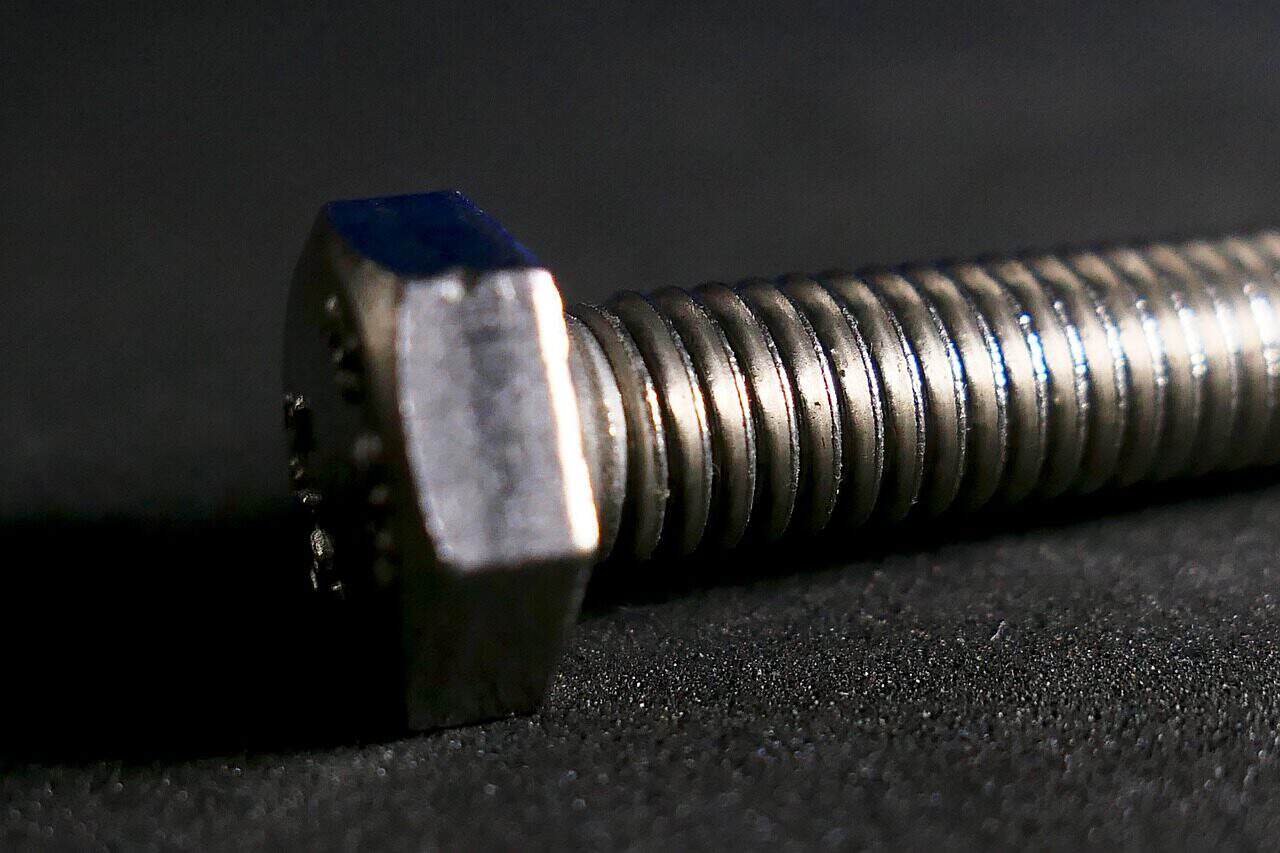
O Haste e a Rosca
A haste é o corpo do parafuso. A parte roscada é projetada para converter o movimento rotacional do torque em movimento linear, o que estica o parafuso e cria tensão. Essa tensão é o que gera a força de aperto que mantém a junta unida. As roscas são especificadas pelo passo, sendo que roscas grossas (como UNC) permitem uma montagem mais rápida e são mais tolerantes a pequenos danos, enquanto roscas finas (como UNF) oferecem resistência ligeiramente maior e ajuste mais preciso. A precisão do formato da rosca é fundamental para uma relação previsível entre torque e tensão.
Ciência da Resistência de Junta
Criar uma junta aparafusada segura é uma ciência exata controlada pela interação de torque, atrito e tensão. A forma única de um parafuso de flange é especificamente projetada para gerenciar essas forças com maior previsibilidade e controle do que um fixador padrão. Compreender essa relação é a chave para projetar e manter a resistência da junta.
O objetivo final de apertar um parafuso não é atingir um valor de torque específico, mas criar uma quantidade precisa de tensão no parafuso, conhecida como pré-carga ou força de aperto. Essa força de aperto é o que mantém o conjunto unido, resiste às forças externas e evita o afrouxamento. Torque é apenas a entrada rotacional que aplicamos para alcançar essa força linear. A relação pode ser simplificada pela fórmula:
`T = K * D * F`
Onde:
- `T` = Torque Aplicado
- `K` = Fator de Porca (um número que leva em conta todo o atrito)
- `D` = Diâmetro do Parafuso
- `F` = Pré-carga Desejada (Força de Aperto)
A flange desempenha um papel fundamental em tornar o fator ‘K’ mais consistente. Ao fornecer uma grande superfície de contato lisa e uniformemente acabada sob a cabeça, ela estabiliza uma das maiores variáveis na equação: o atrito sob a cabeça. Isso leva a uma conversão mais precisa e repetível do torque na força de aperto desejada.
Como Torque e Tensão Trabalham Juntos
Quando o torque é aplicado a um parafuso de flange, toda a energia não se transforma em força de aperto útil. Uma parte significativa é usada para combater o atrito. Uma divisão típica da energia do torque de entrada é:
- Cerca de 50% é perdido devido ao atrito entre a flange e a superfície que ela toca.
- Cerca de 40% é perdido devido ao atrito entre as roscas macho e fêmea.
- Apenas cerca de 10% do torque de entrada resulta em alongamento útil do parafuso, criando a força de aperto.
Essa divisão mostra por que controlar o atrito é tão importante. A área de contato consistente e o acabamento da flange ajudam a normalizar o atrito sob a cabeça, tornando o 10% útil mais previsível. Sem esse controle, mudanças na rugosidade da superfície ou sujeira poderiam alterar drasticamente a pré-carga alcançada para um torque dado, levando a uma junta solta ou a um fixador apertado demais, danificado.
Criando a Melhor Força de Aperto
A grande diâmetro da flange é sua vantagem mais óbvia. Ela distribui a força de aperto sobre uma área muito maior em comparação com a cabeça de um parafuso padrão. Isso reduz a pressão de contato, medida em libras por polegada quadrada (psi) ou megapascais (MPa). Os benefícios são duplos:
- Previne Danos ao Material: Em materiais mais macios, como ligas de alumínio, plásticos ou chapas metálicas finas, a alta pressão de contato de uma cabeça de parafuso pequena pode causar deformação local, esmagamento ou trincas. A flange reduz esse risco, preservando a integridade das peças presas.
- Melhora a Rigidez da Junta: Ao envolver uma área maior do material do encaixe, a flange pode aumentar a rigidez geral da região fixada, o que é benéfico em aplicações sujeitas a cargas variáveis ou repetidas.
Ciência e seleção de materiais
Escolher o material e o revestimento corretos para um parafuso de flange é tão importante quanto calcular o torque adequado. O processo de seleção é um equilíbrio cuidadoso entre resistência mecânica, resistência ambiental, tolerância à temperatura e custo. Um fixador que é perfeitamente especificado para resistência pode falhar precocemente se não conseguir suportar o ambiente corrosivo de sua aplicação.
A escolha do material impacta diretamente a capacidade de carga do fixador. Para fixadores de aço, isso é definido por classes de propriedade de acordo com normas como a ISO 898-1. Essas classes determinam a resistência à tração máxima e a resistência ao escoamento do material. Além disso, a compatibilidade de materiais entre o parafuso e os materiais fixados é essencial para evitar a corrosão galvânica, um processo eletroquímico que ocorre quando metais diferentes entram em contato na presença de umidade.
Graus de Aço Carbono e Liga
Aços carbono e liga são os materiais mais comuns para parafusos de flange de alta resistência. Suas propriedades são definidas por um sistema de classes numéricas. Por exemplo:
- Classe de Propriedade 8.8: Um aço carbono médio, aquecido e resfriado para resistência. Possui uma resistência à tração mínima (UTS) de 800 MPa e uma resistência ao escoamento que é 80% de sua UTS (640 MPa). Este é um grau de trabalho para aplicações gerais automotivas e maquinaria industrial.
- Classe de Propriedade 10.9: Um aço liga, aquecido e resfriado para resistência. Oferece maior resistência com uma UTS de 1000 MPa e uma resistência ao escoamento de 900 MPa. É utilizado em aplicações que requerem maior pré-carga e cargas de aperto, como peças de suspensão ou conexões estruturais.
- Classe de Propriedade 12.9: A mais alta classe de resistência padrão, feita de aço liga. Possui uma UTS de 1200 MPa e uma resistência ao escoamento de 1080 MPa, reservada para as aplicações mais exigentes, como peças de motores de alto desempenho.
Variedades de Aço Inoxidável
Quando a resistência à corrosão é a principal preocupação, o aço inoxidável é o material de escolha. As duas variedades mais comuns usadas para parafusos de flange são:
- Aço Inoxidável 304 (A2): Um tipo de aço com excelente resistência à corrosão na maioria das condições atmosféricas e contra muitos produtos químicos. É amplamente utilizado em equipamentos de processamento de alimentos, tanques químicos e aplicações arquitetônicas.
- Aço Inoxidável 316 (A4): Também um tipo semelhante de aço, mas com a adição de molibdênio. Isso proporciona resistência superior à corrosão, especialmente contra cloretos e ambientes marinhos. É a escolha preferida para hardware marítimo, processamento químico e instalações costeiras.
Revestimentos e acabamentos
Revestimentos são aplicados aos fixadores, particularmente aos de aço carbono e liga, para fornecer resistência à corrosão e, em alguns casos, modificar as características de fricção. Acabamentos comuns incluem:
- Revestimento de Zinco: Uma camada fina de zinco fornece proteção sacrificial contra corrosão. É econômico, mas oferece resistência limitada em ambientes severos. Um revestimento de conversão de cromo (como transparente, amarelo ou preto) é frequentemente aplicado sobre o zinco para proteção adicional.
- Galvanização por imersão a quente: Este processo envolve mergulhar o fixador em zinco fundido, criando uma camada de proteção muito mais espessa e durável. É adequado para aplicações externas e industriais, mas pode afetar o encaixe da rosca se não for devidamente considerado.
- Revestimentos Proprietários: Muitos fabricantes oferecem revestimentos especializados (como floco de zinco, fosfato) que proporcionam resistência aprimorada à corrosão (frequentemente avaliada em horas de teste de névoa salina) e propriedades de atrito controladas para relações de torque-tensão mais precisas.
Tabela 1: Guia de Seleção de Material para Parafuso de Flange
| Material / Revestimento | Propriedades Chave (Resistência, Corrosão) | Aplicativos comuns | Considerações / Limitações |
| Aço Classe 8.8 | Alta resistência, Baixa resistência à corrosão (requer revestimento) | Máquinas gerais, chassis automotivos, montagem estrutural | Enferruja rapidamente sem revestimento protetor. |
| Aço Classe 10.9 | Resistência Muito Alta, Baixa resistência à corrosão (requer revestimento) | Componentes de motor, suspensão, juntas de alta carga | Mais frágil que 8.8; requer controle cuidadoso de torque. |
| Aço Inoxidável 304 (A2) | Resistência Moderada, Excelente resistência à corrosão | Equipamentos de alimentos, arquitetura, processamento químico | Resistência inferior à de aços ligantes; suscetível a pitting por cloreto. |
| Aço Inoxidável 316 (A4) | Resistência Moderada, Resistência Superior à Corrosão (Cloreto/Marinha) | Ferramentas marítimas, estruturas costeiras, dispositivos médicos | Mais caro que o 304; menor resistência que os aços ligantes. |
| Revestimento de zinco | Barreira de corrosão sacrificial para aço; pode afetar o atrito | Eletrônicos internos, automotivos de uso leve, uso geral | Vida útil limitada em ambientes externos ou úmidos. |
| Galvanização a Quente | Proteção contra corrosão espessa e durável para aço | Construção ao ar livre, infraestrutura, utilidades | Revestimento espesso pode interferir no encaixe da rosca; requer porcas de tamanho maior. |
Análise Avançada: Serrilhado vs. Liso
Enquanto uma flange lisa é excelente para distribuir carga e proteger superfícies, um parafuso de flange serrilhada é uma solução engenheirada para um problema mais desafiador: afrouxamento por vibração. Em ambientes dinâmicos, onde os conjuntos estão sujeitos a vibração, choque ou variações de temperatura, as juntas aparafusadas podem perder pré-carga e falhar. Esse fenômeno, conhecido como autoafrouxamento, é uma causa primária de falha mecânica.
O parafuso de flange serrilhada combate isso diretamente. Ele vai além de confiar apenas no atrito da força de aperto e introduz um mecanismo de travamento mecânico. As serras afiadas e anguladas na parte inferior da flange são projetadas para cavar na superfície ao serem apertadas. Isso cria uma interferência positiva que resiste à contra-rotação. Pela experiência, as marcas de mordida deixadas na superfície de uma junta após a desmontagem não são um sinal de dano, mas uma evidência clara de que a função de travamento foi realizada corretamente.
Esse travamento mecânico vem com uma troca significativa: marcas na superfície. As serras ficarão permanentemente embutidas no material. Isso torna os parafusos de flange serrilhada inadequados para superfícies estéticas, aplicações que requerem desmontagem e remontagem frequentes ou em materiais macios que possam ser excessivamente danificados. Para essas aplicações, um parafuso de flange lisa, que depende de alta pré-carga e atrito, é a escolha adequada.
Como Funciona o Autoafrouxamento
O autoafrouxamento ocorre devido a pequenos escorregamentos laterais repetidos entre as superfícies presas e entre as roscas do parafuso. Cada microdeslizamento permite uma pequena rotação reversa. Ao longo de milhares ou milhões de ciclos, essas pequenas rotações se acumulam, reduzindo a tensão do parafuso e causando o afrouxamento da junta. O principal fator não é o afrouxamento da cabeça do parafuso contra a junta, mas o deslizamento dentro das roscas. No entanto, resistir à rotação na cabeça é uma medida altamente eficaz de prevenção.
Como as Serrilhas Criam o Travamento
As serrilhas em um parafuso de flange são anguladas como um catraca. Elas são projetadas para deslizar sobre a superfície na direção de aperto, mas cavar e resistir à rotação na direção de afrouxamento. Quando a pré-carga suficiente é aplicada, a alta pressão força as bordas afiadas das serrilhas a se embutirem no material da junta. Para afrouxar, o parafuso deve subir dessas ranhuras — o que é impedido pela carga de aperto — ou shearar uma pequena quantidade do material, ambos exigindo energia significativa e resistindo ao torque de afrouxamento induzido pela vibração.
Guia de Aplicação: Quando Escolher
A escolha entre uma flange serrilhada e uma lisa é determinada pelo ambiente de aplicação e pelos requisitos de serviço.
- Escolha Parafusos de Flange Serrilhada para: Ambientes de alta vibração, como suportes de motor, estruturas de máquinas pesadas, ferramentas elétricas e equipamentos industriais, onde a segurança das juntas é mais importante e a aparência da superfície é secundária.
- Escolha Parafusos de Flange Lisa para: Aplicações de carga estática, fixação em materiais macios (plásticos, alumínio), superfícies acabadas ou pintadas, invólucros eletrônicos e montagens que requerem desmontagem periódica sem dano à superfície.
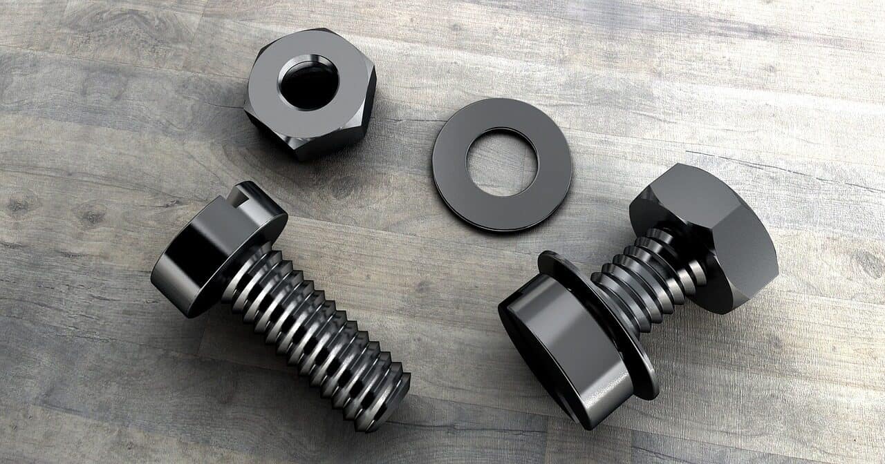
Tabela 2: Matriz de Aplicação de Parafusos de Flange Serrilhados vs. Lisa
| Atributo | Flange Serrilhado | Flange Lisa |
| Resistência à Vibração | Excelente; fornece uma trava mecânica contra o afrouxamento por si só. | Bom; depende de alta pré-carga e fricção para resistir ao afrouxamento. |
| Preservação da Superfície | Fraco; projetado para marcar a superfície de acoplamento para criar uma trava. | Excelente; distribui a carga sem danificar a superfície da junta. |
| Reutilizabilidade | Limitado; a eficácia pode diminuir a cada uso à medida que as superfícies se desgastam. | Alta; pode ser reutilizado várias vezes se as roscas estiverem intactas. |
| Casos de Uso Típicos | Motores, máquinas vibratórias, estruturas, equipamentos de energia. | Eletrônicos, painéis acabados, materiais macios (plástico/alumínio), cargas estáticas. |
| Fricção sob a cabeça | Maior e mais variável devido à ação de corte das serrilhas. | Menor e mais consistente, permitindo uma relação de torque-tensão mais precisa. |
Guia Técnico de Falhas na Fixação
Mesmo com um projeto adequado, a fixação com parafusos de flange pode falhar. Uma abordagem sistemática para diagnosticar essas falhas é essencial para qualquer engenheiro ou técnico. As falhas raramente são aleatórias; são sintomas de um problema subjacente no projeto, na seleção de materiais ou no procedimento de montagem. Ao entender os modos comuns de falha, podemos implementar medidas preventivas eficazes. Esta seção serve como um guia de diagnóstico para identificar e corrigir problemas em juntas aparafusadas usando parafusos de flange.
Modo de Falha 1: Sobrecarga do Parafuso
Essa falha ocorre quando a tensão no parafuso excede a resistência do material, causando sua deformação permanente (alongamento) ou fratura.
- Causa: A causa mais comum é o torque excessivo aplicado durante a montagem, que gera uma pré-carga maior que a carga de prova do parafuso. Utilizar um parafuso com grau de resistência insuficiente para a carga de aperto requerida é outra causa principal.
- Identificação: Um parafuso fraturado (frequentemente uma cisalha limpa em 45 graus para falha por tração), roscas desgastadas na porca ou no furo roscado, ou uma cabeça que se desprendeu. Um parafuso deformado pode às vezes ser identificado medindo seu comprimento e verificando se ele foi alongado permanentemente.
- Prevenção: Sempre use uma chave de torque calibrada. Siga rigorosamente as especificações de torque calculadas para o tamanho, grau e condição de lubrificação do parafuso. Certifique-se de que a classe de propriedade do parafuso (como 8.8, 10.9) esteja corretamente especificada com base nos cálculos de carga de engenharia.
Modo de Falha 2: Carga de Aperto Insuficiente
Este talvez seja o modo de falha mais comum e sorrateiro, pois leva ao afrouxamento da junta, escorregamento ou vazamento ao longo do tempo.
- Causa: O aperto insuficiente é a causa mais direta. No entanto, outros fatores podem levar a uma baixa pré-carga mesmo quando o torque “correto” é aplicado. Estes incluem fricção excessiva devido a roscas sujas, danificadas ou não lubrificadas, uso do fator “K” incorreto nos cálculos de torque, ou relaxamento (assentamento) do material macio ou juntas de vedação após o aperto inicial.
- Identificação: O fixador fica solto em serviço. Em uma junta selada, isso se manifesta como vazamento de fluido ou gás. Em uma junta estrutural, pode levar à corrosão por atrito (um pó de cor marrom-avermelhada ou preta ao redor da junta) ou à falha por fadiga eventual do parafuso.
- Prevenção: Garanta que as roscas estejam limpas e em boas condições. Use lubrificantes especificados, se necessário, conforme procedimento de montagem. Aplique torque usando uma ferramenta calibrada e uma técnica adequada e suave. Para juntas com juntas de material macio ou propensas ao relaxamento, recomenda-se uma sequência de reaperto após um período inicial de assentamento. Em ambientes de alta vibração, considere usar um parafuso de flange serrilhada.
Modo de Falha 3: Dano ao Substrato
Essa falha envolve dano ao material sendo prensado, não ao parafuso em si.
- Causa: Normalmente ocorre quando um parafuso sem flange é usado em material macio, ou quando a flange do parafuso escolhido é muito pequena para a carga e resistência à compressão do material. A alta tensão de contato sob a cabeça do parafuso amassa ou trinca o material.
- Identificação: Trincas visíveis, crateras ou indentação do material da junta ao redor da cabeça do parafuso. A junta pode parecer solta porque o material cedeu, reduzindo a pré-carga do parafuso.
- Prevenção: Este é o principal problema que os parafusos de flange foram projetados para resolver. Sempre use um parafuso de flange ao fixar em plásticos, compósitos, alumínio e chapas metálicas finas. Para aplicações críticas, calcule a tensão de contato (Força de Aperto / Área de Contato da Flange) e garanta que esteja bem abaixo da resistência à deformação por compressão do material.
Tabela 3: Guia de Solução de Problemas para Falhas na Fixação com Parafuso de Flange
| Sintoma | Causa(s) Provável(eis) | Ação de Diagnóstico | Solução Corretiva |
| Fixador está solto ou saiu do lugar | 1. Pré-carga insuficiente (aperto abaixo do torque recomendado).<br>2. Vibração severa.<br>3. Relaxamento da junta. | 1. Verifique o torque em fixadores falhados e adjacentes.<br>2. Inspecione sinais de vibração.<br>3. Verifique a compressão da junta ou o afrouxamento de material macio. | 1. Recalcule e aplique o torque correto com uma chave calibrada.<br>2. Troque por um parafuso de flange serrilhada ou adicione um trava-rosca químico.<br>3. Reaplique o torque após um período de amaciamento. |
| Parafuso está fraturado (cabeça desgastada) | 1. Aperto excessivo.<br>2. Grau de parafuso incorreto (muito fraco).<br>3. Fragilização por hidrogênio (parafusos de alta resistência). | 1. Revisar as especificações de torque de montagem e registros de calibração das ferramentas.<br>2. Verificar as marcações das porcas para a classe de propriedade.<br>3. Revisar o processo de galvanização/revestimento. | 1. Reduza o torque para o valor especificado.<br>2. Reespecifique um parafuso de grau superior (como 8.8 para 10.9).<br>3. Use materiais/revestimentos não suscetíveis à embrittlement. |
| Fluido ou gás está vazando da junta | 1. Carga de aperto insuficiente.<br>2. Carga de aperto desigual (padrão de aperto incorreto).<br>3. Junta danificada. | 1. Verifique o torque de todos os fixadores.<br>2. Inspecione a compressão uniforme da junta.<br>3. Desmonte e inspecione a superfície da junta. | 1. Reaplique o torque em todos os fixadores conforme especificação.<br>2. Aperte os fixadores em padrão de estrela ou cruzado.<br>3. Substitua a junta e garanta que as superfícies estejam limpas. |
| Material ao redor da cabeça do parafuso está rachado | 1. Sobrecarga excessiva do rolamento.<br>2. Uso de parafuso sem flange em material macio. | 1. Inspecione a área ao redor da cabeça do parafuso.<br>2. Verifique o tipo de fixador utilizado. | 1. Use um parafuso de flange com diâmetro maior de flange.<br>2. Reduza a carga do braçadeira, se possível.<br>3. Substitua o parafuso padrão por um parafuso de flange. |
| Roscas estão desgastadas | 1. Aperto excessivo.<br>2. Rosqueamento cruzado durante a montagem.<br>3. Passo de rosca incompatível. | 1. Inspecione as roscas macho e fêmea.<br>2. Verifique sinais de entrada forçada e inclinada. | 1. Reduza o torque; use uma ferramenta com limite de torque.<br>2. Garanta o alinhamento adequado antes de apertar; comece manualmente.<br>3. Substitua o elemento de fixação/porca pela rosca correta. |
Conclusão: Juntando Tudo
Esta análise nos levou desde as partes básicas de um parafuso de flange até a ciência complexa da resistência da junta e as realidades práticas da análise de falhas. Vimos que a seleção e o uso do fixador de parafuso de flange é um processo baseado em princípios de engenharia fundamentais. Requer uma compreensão abrangente de forças, materiais e condições ambientais.
O tema central é que um parafuso de flange não é apenas uma peça básica, mas um componente projetado. Sua flange integrada é uma escolha de design deliberada para gerenciar o estresse, controlar variáveis de atrito e, no caso de designs serrilhados, combater ativamente a ameaça persistente de afrouxamento por vibração. Aplicar o torque correto é apenas uma parte do quebra-cabeça; alcançar a carga de aperto correta e estável é o objetivo final. Ao dominar os princípios de seleção de materiais, entender a relação torque-tensão e ser capaz de diagnosticar modos de falha, podemos usar todo o potencial dos parafusos de flange para projetar montagens mecânicas que sejam seguras, duráveis e confiáveis.
- https://www.iso.org/ ISO - Organização Internacional de Padronização
- https://en.wikipedia.org/wiki/ISO_898 Wikipedia – Normas ISO 898 para Fixadores
- https://indfast.org/ Instituto de Fixadores Industriais
- https://www.sae.org/ SAE International – Normas de Fixadores
- https://www.astm.org/ ASTM International - Padrões de teste de fixadores
- https://ntrs.nasa.gov/ Relatórios Técnicos da NASA – Manual de Design de Fixadores
- https://www.engineersedge.com/ Engineers Edge – Recursos de Torque e Fixadores
- https://www.sciencedirect.com/ ScienceDirect – Pesquisa em Fixadores Mecânicos
- https://webstore.ansi.org/ ANSI - Instituto Nacional de Padrões Americanos
- https://www.researchgate.net/ ResearchGate – Artigos de Engenharia de Fixadores


