Guía del ingeniero sobre conexiones de torres: Una inmersión profunda en los principios técnicos
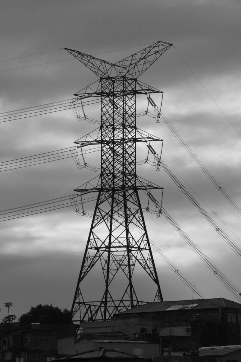
En ingeniería estructural, una conexión de torre es el conjunto de piezas que une diferentes piezas estructurales, como patas, tirantes o secciones de una torre. Su función principal es transferir las cargas calculadas -incluidas las de tracción, compresión y cizallamiento- entre estas piezas, asegurándose de que toda la estructura se mantiene estable, fuerte y funciona como una unidad. Ya se trate de un monoposte de telecomunicaciones, una torre de celosía de transmisión eléctrica o una estructura de observación, la conexión es el eslabón más importante de la cadena estructural. Un fallo en un solo punto de conexión puede provocar el derrumbe de toda la torre. Este artículo ofrece un análisis técnico completo de los principios, tipos, materiales y consideraciones de diseño que hacen que las conexiones de las torres sean fuertes y fiables.
Examinaremos en detalle los siguientes temas clave:
- Tipos básicos de conexión y sus usos específicos.
- Principios de la ciencia de los materiales y criterios de selección del acero y los elementos de fijación.
- Principios básicos de diseño, análisis de cargas y normas industriales aplicables.
- Modos habituales de fallo y mejores prácticas de inspección y mantenimiento.
- Futuras innovaciones en tecnología de conexión y control de la salud estructural.
Una clasificación completa de las conexiones
Conocer los principales tipos de torre conexiones es esencial para cualquier ingeniero que intervienen en el diseño, el análisis o el mantenimiento de las torres. Cada método tiene características mecánicas, ventajas y limitaciones distintas que determinan su idoneidad para una aplicación determinada. La elección del tipo de conexión influye no sólo en el rendimiento estructural, sino también en el coste de fabricación, construcción y mantenimiento a largo plazo. A continuación, clasificamos y explicamos los principales tipos de conexión utilizados en la construcción de torres modernas.
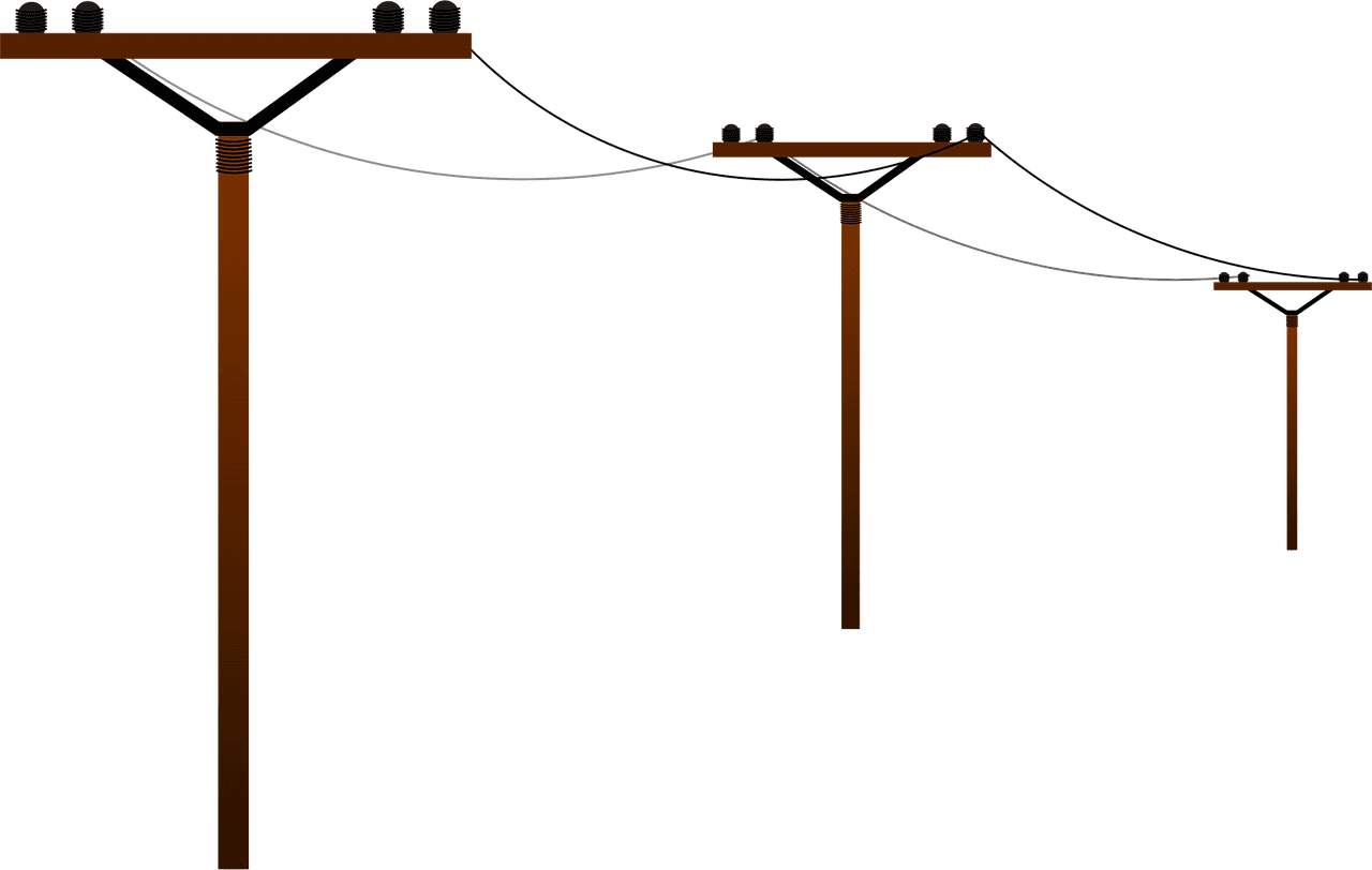
Conexiones atornilladas
Las uniones atornilladas son el método más común en la construcción de torres, especialmente para el montaje sobre el terreno, porque son fiables y fáciles de instalar. A grandes rasgos, se clasifican en dos categorías en función de cómo transfieren las cargas.
Las uniones de tipo rodamiento están diseñadas para transferir la carga principalmente a través del cizallamiento en los pernos y el rodamiento en el material de las piezas conectadas. Al aplicar la carga, las piezas pueden deslizarse hasta que el vástago del perno entra en contacto con los laterales de los orificios del perno. En este punto, la carga se transfiere directamente. Este tipo es más sencillo de diseñar e instalar, pero es más probable que se afloje bajo cargas vibratorias y tiene menor resistencia a la fatiga. La posibilidad de que los orificios se estiren en caso de inversión repetida de la carga lo hace menos adecuado para juntas que experimentan cambios de carga significativos. Suelen utilizarse para arriostramientos secundarios o juntas menos críticas en una estructura de celosía.
Las uniones de tipo fricción, también conocidas como uniones de deslizamiento crítico, son la norma industrial para las uniones estructurales principales. En este diseño, los pernos de alta resistencia se aprietan hasta un valor mínimo especificado, creando una fuerza de sujeción significativa entre las superficies en contacto de las placas conectadas. La carga se transfiere por la fricción estática creada por esta fuerza de apriete. La conexión está diseñada para que las cargas de servicio aplicadas no superen esta resistencia a la fricción, evitando el deslizamiento en la unión. Esto elimina los problemas de estiramiento de los orificios y proporciona un rendimiento superior bajo cargas cíclicas y dinámicas, lo que la hace ideal para resistir la fatiga. Entre los subtipos más comunes se encuentran las conexiones de placa con brida, habituales en monopolos y torres tubulares para unir secciones, y las conexiones solapadas, estándar para unir los miembros angulares de una torre de celosía.
Conexiones soldadas
Las conexiones soldadas crean uniones sólidas y continuas mediante la fusión del metal de las piezas conectadas. Esto da como resultado una conexión rígida de gran resistencia y aspecto limpio, ya que elimina la necesidad de placas de refuerzo y pernos.
La principal distinción es entre soldaduras en taller y soldaduras en campo. Las soldaduras en taller se realizan en un entorno de fábrica controlado, lo que permite una calidad superior. control de calidadEn general, se obtienen soldaduras de mayor calidad y más rentables. El resultado suele ser una soldadura de mayor calidad y más rentable. Las soldaduras de campo se realizan in situ, a menudo en condiciones difíciles, lo que complica control de calidad y aumenta los costes. La soldadura in situ suele reservarse para reparaciones o situaciones en las que no es factible transportar grandes secciones premontadas.
Los tipos de soldadura más comunes en las aplicaciones de torres son las soldaduras de filete, que se utilizan para unir placas solapadas o sujetar miembros a placas de refuerzo, y las soldaduras a tope (normalmente de penetración total), que se utilizan para unir los extremos de los miembros, como en la fabricación de secciones de postes tubulares. A pesar de su resistencia, las uniones soldadas plantean problemas. Tienen más probabilidades de sufrir fallos por fatiga debidos a defectos microscópicos de la soldadura, y las tensiones residuales causadas por el proceso de soldadura pueden afectar al rendimiento. La inspección también es más compleja, y a menudo requiere métodos de ensayos no destructivos (END) para garantizar la integridad. Además, las reparaciones sobre el terreno de las uniones soldadas son bastante más difíciles que sustituir un perno.
Conexiones con pasadores y bisagras
Las uniones articuladas o con pasador están diseñadas para permitir la rotación alrededor de un solo eje, al tiempo que impiden la traslación en dos ejes. La carga se transfiere mediante cizallamiento y apoyo en un pasador de gran diámetro. Este tipo de conexión se modela en el análisis como una bisagra ideal, lo que simplifica el cálculo de las fuerzas dentro de la estructura al evitar la transferencia de momentos de flexión a través de la articulación.
Su aplicación en torres es especializada. Lo más habitual es encontrarlos en la base de algunos mástiles arriostrados o torres autoportantes, lo que permite que la estructura gire ligeramente bajo carga y simplifica el diseño de los cimientos. También pueden utilizarse en diseños específicos de torres articuladas o como parte de mecanismos para subir y bajar una torre. Los principales problemas de diseño de las conexiones con pasadores son las elevadas concentraciones de esfuerzos que se producen en el orificio del pasador y el posible desgaste de las superficies del pasador y del orificio con el paso del tiempo.
Análisis comparativo de las conexiones
Para ofrecer una visión general clara, la siguiente tabla compara los atributos clave de cada método de conexión primaria. Esto permite a los ingenieros tomar decisiones fundamentadas en función de las exigencias específicas de su proyecto.
| Tipo de conexión | Transferencia de carga primaria | Casos de uso común | Ventajas | Desventajas |
| Atornillado (fricción) | Fricción entre placas | Bridas de monopolo, torres de celosía | Alta fiabilidad, reemplazable, buena resistencia a la fatiga | Requiere un apriete preciso, posibilidad de que se aflojen los tornillos |
| Atornillado (rodamiento) | Cizallamiento en los pernos | Arriostramiento secundario, juntas menos críticas | Diseño e instalación más sencillos | Menor resistencia a la fatiga, posibilidad de ovalización del orificio |
| Soldado | Metal fundido | Placas base, secciones fabricadas en taller | Gran rigidez, estética limpia | Difícil reparación sobre el terreno, requiere END, susceptible a la fatiga |
| Pinned | Rodamiento sobre pasador | Bases de torres, estructuras especializadas | Permite la rotación, simplifica el análisis | Tensión concentrada en el orificio, sujeta a desgaste |
La ciencia de los materiales
El rendimiento y la seguridad a largo plazo de una conexión de torre dependen directamente de los materiales con los que se construye. La selección del acero adecuado para los elementos y las placas, junto con el grado correcto de los elementos de fijación, es un paso crítico del diseño que se rige por normas industriales establecidas y por un profundo conocimiento de la ciencia de los materiales. Las principales consideraciones son la resistencia, la ductilidad, la soldabilidad y, lo que es más importante, la resistencia a los daños medioambientales.
Acero estructural de alta resistencia
La gran mayoría de las conexiones de torres utilizan acero estructural para placas, cartelas y elementos. El grado específico se elige para equilibrar la resistencia, el coste y la capacidad de fabricación. Los grados más comunes especificados por la Sociedad Americana de Pruebas y Materiales (ASTM) incluyen:
- ASTM A36: Acero estructural al carbono con un límite elástico mínimo de 36 ksi (250 MPa). Es un acero rentable de uso general con una excelente soldabilidad y se utiliza a menudo para componentes menos críticos, placas de refuerzo o en diseños de torres más antiguos.
- ASTM A572 Grado 50: Acero de alta resistencia y baja aleación (HSLA) con un límite elástico mínimo de 50 ksi (345 MPa). Su mayor relación resistencia-peso en comparación con el A36 permite diseños más ligeros y eficientes, lo que lo convierte en una opción habitual para los principales elementos estructurales y placas de conexión de las torres modernas.
- ASTM A992: Este acero ha sustituido en gran medida al A572 Grado 50 para perfiles estructurales de ala ancha. Tiene un límite elástico especificado de 50-65 ksi (345-450 MPa) y se controla para obtener una relación máxima entre el límite elástico y la resistencia a la tracción, lo que proporciona un mejor rendimiento en aplicaciones sísmicas.
El papel fundamental de los pernos
En las uniones atornilladas, los elementos de fijación son posiblemente los componentes más críticos. Los pernos estructurales de alta resistencia están diseñados específicamente para este fin. Las dos normas ASTM principales son:
- ASTM A325 / A325M: Son pernos estructurales estándar de alta resistencia fabricados con acero de carbono medio. Tienen una resistencia mínima a la tracción de 120 ksi (825 MPa) para diámetros de hasta 1 pulgada. Están diseñados para su uso tanto en conexiones con cojinetes como en conexiones con deslizamiento crítico.
- ASTM A490 / A490M: Se trata de tornillos de mayor resistencia fabricados con acero aleadocon una resistencia mínima a la tracción de 150 ksi (1035 MPa). Se utilizan en aplicaciones que requieren una mayor fuerza de tensión previa y de apriete o cuando el tamaño de la conexión debe reducirse al mínimo. Son más frágiles que los tornillos A325 y tienen restricciones específicas en cuanto a la galvanización.
Es esencial utilizar una fijación completa sistema en el que las tuercas y arandelas se adaptan al grado del perno. Las tuercas ASTM A563 y las arandelas F436 se especifican para su uso con pernos A325 y A490 para garantizar que el conjunto pueda desarrollar la tensión necesaria sin fallos.
Protección contra la corrosión
Dado que las torres están expuestas a la intemperie durante décadas, la protección contra la corrosión no es una ocurrencia tardía, sino una consideración primordial en el diseño. El método más eficaz y utilizado para la protección de las conexiones de acero es el galvanizado en caliente. En este proceso, los componentes de acero fabricados se sumergen en un baño de zinc fundido. El zinc forma una unión metalúrgica con el acero, creando un revestimiento duradero y resistente a la abrasión que proporciona protección catódica y de barrera. El proceso y el grosor del revestimiento se rigen por normas como la ASTM A123 para productos de acero estructural y la ASTM A153 para herrajes como pernos y tuercas.
En algunos entornos o por razones estéticas, pueden utilizarse sistemas de pintura y revestimiento además o en lugar de la galvanización. Estos sistemas multicapa suelen constar de una imprimación rica en zinc, una capa intermedia y una capa superior duradera.
Una preocupación crítica en las conexiones es el potencial de corrosión por hendiduras, que puede producirse en los espacios estrechos entre placas, y la corrosión galvánica, que puede ocurrir si metales diferentes están en contacto en presencia de un electrolito. Un diseño adecuado y selección de materialesLa utilización de elementos de fijación galvanizados con acero galvanizado, por ejemplo, reduce estos riesgos.
Propiedades de Material Design
La siguiente tabla resume las principales propiedades mecánicas de los materiales utilizados habitualmente en las conexiones de las torres, proporcionando una referencia para los ingenieros de diseño.
| Material (norma ASTM) | Tipo de componente | Mínimo límite elástico (ksi / MPa) | Resistencia mínima a la tracción (ksi / MPa) | Característica clave |
| Acero A36 | Placas, ángulos | 36 / 250 | 58-80 / 400-550 | Uso general, buena soldabilidad |
| Acero A572 Grado 50 | Placas, formas | 50 / 345 | 65 / 450 | Mayor relación resistencia/peso que el A36 |
| Tornillo A325 | Pernos | 85 ó 92 / 585 ó 635 | 120 / 825 | Tornillo estructural estándar de alta resistencia |
| Tornillo A490 | Pernos | 115 ó 120 / 795 ó 825 | 150 / 1035 | Mayor resistencia para cargas más exigentes |
Principios básicos de ingeniería
El diseño de una conexión de torre es un cuidadoso proceso basado en los principios de la ingeniería y se rigen por códigos específicos del sector. Un diseño satisfactorio garantiza que se han tenido en cuenta todos los modos de fallo potenciales y que la conexión tiene capacidad suficiente para resistir las cargas factorizadas que experimentará a lo largo de su vida útil. Esta sección se adentra en el núcleo técnico del diseño de conexiones.
Comprender las rutas de carga
El primer paso en el diseño de cualquier conexión es comprender las fuerzas que debe transferir. Las cargas sobre una torre -incluidas las cargas muertas (peso propio), las cargas de hielo y las cargas dinámicas del viento- se calculan para toda la estructura. A continuación, estas fuerzas globales se descomponen en fuerzas axiales (tensión o compresión) y fuerzas de corte en los elementos individuales que se unen en una conexión. El propósito de la conexión es proporcionar una trayectoria de carga continua para estas fuerzas. Por ejemplo, en una torre de celosía, la fuerza de compresión de una riostra diagonal debe transferirse a través de una placa de refuerzo hasta la pata principal de la torre. Para dimensionar correctamente las placas, las soldaduras y los pernos es esencial comprender claramente esta trayectoria.
Códigos de diseño como el TIA-222-H (Norma estructural para estructuras de soporte de antenas y antenas) o el Eurocódigo 3 (Diseño de estructuras de acero) proporcionan métodos para determinar estas cargas y especifican combinaciones de carga. Estas combinaciones emparejan diferentes tipos de carga (por ejemplo, 1,2 * Carga muerta + 1,6 * Carga de viento) para simular los peores escenarios, y la conexión debe diseñarse para resistir las fuerzas resultantes de cada combinación gobernante.
Tensión, deformación y fallo
Una conexión debe comprobarse frente a varios modos de fallo potenciales. Cada modo corresponde a un tipo específico de tensión que supera la capacidad del material.
- Tensión: Las fuerzas de tracción pueden causar el fallo por fractura del perno o por elasticidad y posterior fractura de las placas conectadas (fractura de la sección neta).
- Cizallamiento: Las fuerzas de cizallamiento actúan cortando un tornillo. El diseño debe garantizar que la resistencia al cizallamiento del tornillo sea la adecuada. En las placas, el cizallamiento en bloque es un modo de fallo que implica una combinación de cizallamiento a lo largo de un plano y tensión en un plano perpendicular.
- Rodamiento: Se trata de un fallo por aplastamiento que se produce cuando el vástago de un perno ejerce una presión excesiva contra el lateral de su orificio, provocando su alargamiento o desgarro. El diseño limita la tensión de apoyo en la zona proyectada del perno.
- Flexión: En conexiones como las bridas de monopostes, las cargas excéntricas pueden provocar una acción de palanca, lo que crea flexión y tensión adicionales en los pernos más allá de la carga inicial aplicada. Esta fuerza de apalancamiento debe tenerse en cuenta en el diseño.
- Fatiga: Las cargas cíclicas, normalmente debidas a vibraciones inducidas por el viento, como el desprendimiento de vórtices, pueden provocar la aparición de grietas microscópicas que crecen con el tiempo y conducen al fallo a un nivel de tensión muy inferior a la resistencia estática a la tracción del material. Las conexiones con deslizamiento crítico y los perfiles de soldadura lisos son fundamentales para mejorar la vida a fatiga.
Física de las juntas de deslizamiento crítico
La fiabilidad de una conexión con deslizamiento crítico depende de que se alcance y mantenga una fuerza de apriete específica. La resistencia nominal al deslizamiento (Rs) de un solo tornillo se calcula mediante la fórmula: Rs = μ * Tb * Ns, donde:
- μ (mu) es el coeficiente de deslizamiento medio de las superficies en contacto. Este valor depende de la preparación de la superficie (por ejemplo, cascarilla de laminación limpia sin pintar, galvanizada).
- Tb es la tensión previa mínima requerida del tornillo, un valor especificado por las normas en función del tamaño y el grado del tornillo.
- Ns es el número de planos de deslizamiento (superficies de contacto) que transfieren la carga.
Para garantizar que se alcanza la tensión previa (Tb) requerida sobre el terreno, es obligatorio aplicar métodos de instalación normalizados. Los más comunes son el método de giro de la tuerca, en el que la tuerca se gira una cantidad específica a partir de una condición de ajuste; el uso de una llave calibrada para aplicar un par objetivo; y el uso de indicadores directos de tensión (DTI), que son arandelas especiales que se deforman visiblemente cuando se alcanza la tensión correcta.
Aplicación del análisis por elementos finitos
Mientras que los cálculos manuales basados en las disposiciones del código son suficientes para las geometrías de conexión estándar, las uniones complejas o no estándar se benefician del Análisis de Elementos Finitos (AEF). El AEF es una potente herramienta informática que permite a los ingenieros crear un modelo digital detallado de la conexión. El modelo se descompone en una malla de pequeños "elementos finitos" y el software resuelve las complejas ecuaciones de tensión y deformación de cada elemento.
El valor del AEF reside en su capacidad para revelar distribuciones de tensiones complejas que no son evidentes a partir de cálculos simplificados. Un gráfico de tensiones codificado por colores a partir de un modelo de AEF puede identificar visualmente los "puntos calientes" de alta tensión, normalmente en las esquinas afiladas o alrededor de los orificios de los pernos. Esto permite al diseñador optimizar la geometría -por ejemplo, añadiendo un radio a una esquina o ajustando el grosor de la placa- para reducir las concentraciones de tensión y mejorar la eficacia y la resistencia a la fatiga de la conexión. Este enfoque moderno representa un nivel superior de análisis de ingeniería, que va más allá de las comprobaciones básicas de los códigos para llegar a una comprensión más fundamental del comportamiento de la conexión bajo carga.
Inspección y mantenimiento
La fiabilidad de una conexión de torre correctamente diseñada e instalada depende de su programa de mantenimiento a largo plazo. La inspección periódica es crucial para identificar y reducir problemas potenciales como la corrosión, el aflojamiento de pernos y las grietas por fatiga antes de que comprometan la integridad estructural. Esta sección proporciona una guía práctica sobre las mejores prácticas de inspección y analiza un modo de fallo común.
Mejores prácticas de inspección
Un programa de inspección exhaustivo incorpora múltiples métodos y es realizado a intervalos regulares por personal cualificado.
La inspección visual es la primera línea de defensa. Los inspectores buscan signos evidentes de deterioro, como vetas de óxido que salgan de los orificios de los pernos o de los bordes de las placas (lo que indica corrosión), revestimientos dañados o descascarillados, placas dobladas o deformadas y huecos visibles entre los elementos conectados.
La inspección física y acústica consiste en comprobar físicamente los componentes. Esto puede incluir la comprobación de pernos con un martillo; un perno apretado emitirá un claro sonido de timbre, mientras que uno flojo producirá un ruido sordo. La comprobación de tuercas y arandelas sueltas o faltantes también es una parte fundamental de este proceso.
Para conexiones críticas o cuando se sospecha un defecto, los ensayos no destructivos (END) proporcionan una evaluación más profunda. Los ensayos con partículas magnéticas (MPT) permiten detectar grietas superficiales en soldaduras y chapas. Los ensayos por ultrasonidos (UT) utilizan ondas sonoras de alta frecuencia para detectar defectos internos en pernos o placas, como grietas de fatiga que aún no han llegado a la superficie.
La siguiente lista de comprobación esboza un plan de inspección rutinaria típico para las conexiones de las torres.
| Inspección | Frecuencia | Método | Buscar | Acción si se encuentra |
| Apriete de pernos | 1-3 años | Visual, Llave dinamométrica | Pernos sueltos/faltantes, óxido | Reapriete o sustituya según las especificaciones |
| Corrosión | Anual | Visual | Óxido, picaduras, fallo del revestimiento | Limpiar y repintar, evaluar la pérdida de sección |
| Grietas estructurales | 1-3 años | Visual, Penetrante | Grietas cerca de soldaduras/orificios de pernos | Revisión técnica inmediata |
| Deformación | Post-evento, Anual | Visual, Medición | Placas dobladas, agujeros alargados | Evaluación técnica necesaria |
| Integridad del revestimiento | Anual | Visual | Descamación, ampollas, caleo | Sistema de revestimiento reparador |
Caso práctico: Apriete incorrecto de pernos
El siguiente escenario, basado en análisis de fallos reales, demuestra cómo un error de procedimiento puede provocar un fallo catastrófico, poniendo de relieve la diferencia entre tener las piezas correctas y utilizar el proceso correcto.
Se trataba de una conexión de un monoposte con brida que falló durante un temporal de viento moderado, muy por debajo de la velocidad del viento prevista. La sección de la torre se dobló en la brida, lo que provocó un colapso estructural completo.
La investigación posterior se centró en la conexión fallida. Se confirmó que los pernos de alta resistencia, las tuercas y las placas de brida eran del material y el tamaño correctos, tal como se especificaba en los planos de diseño. Sin embargo, un análisis forense de las superficies de fractura de los pernos reveló claros indicios de fallo por fatiga, no de una simple sobrecarga por tracción. Una investigación más detallada de los registros de construcción y las entrevistas a la tripulación revelaron que los pernos se habían apretado con una llave de impacto estándar sin ninguna verificación de seguimiento con un método calibrado como el giro de tuerca o una llave dinamométrica. La cuadrilla había asumido que la llave de impacto era suficiente.
El mecanismo de fallo quedó entonces claro. El proceso de apriete no verificado dio lugar a una tensión previa de los pernos muy inferior a la mínima especificada. Esta fuerza de apriete insuficiente hizo que la resistencia a la fricción de la conexión se viera fácilmente superada por las cargas cíclicas del viento. La unión empezó a deslizarse con cada ráfaga de viento. Este deslizamiento sometía a los pernos a esfuerzos repetidos de cizallamiento y flexión, fuerzas para las que no habían sido diseñados. Esta carga cíclica originó grietas de fatiga en las raíces de las roscas de los pernos, que crecieron rápidamente y provocaron el fallo prematuro de todo el grupo de pernos.
La lección de este caso es profunda: en una conexión con deslizamiento crítico, la integridad se deriva de la fuerza de apriete, que es resultado directo del proceso de instalación. Disponer de pernos de alta resistencia carece de sentido si no están bien tensados. Este fallo no se debió a un defecto en el diseño o los materiales, sino a un fallo crítico en el control de calidad de la construcción.
El futuro de la tecnología de conexión
El campo de la ingeniería estructural evoluciona continuamente, y las conexiones de las torres no son una excepción. Las tecnologías emergentes están preparadas para hacer que estos componentes críticos sean más fuertes, más inteligentes y más fáciles de gestionar a lo largo de su ciclo de vida. Estas innovaciones prometen mejorar la seguridad, la resistencia y la rentabilidad de la infraestructura de las torres.
Conexiones y supervisión inteligentes
La tendencia más significativa es la integración de sistemas de control de la salud estructural (SHM) directamente en las conexiones. Se trata de incrustar o fijar sensores para controlar el estado de la conexión en tiempo real. Los sensores de fibra óptica pueden adherirse a las placas para medir la deformación con una precisión increíble, proporcionando una visión directa de las cargas que experimenta la conexión. Los sensores piezoeléctricos pueden detectar emisiones acústicas que pueden indicar el inicio de grietas, mientras que los acelerómetros pueden controlar las vibraciones que podrían provocar fatiga. Estos datos pueden transmitirse de forma inalámbrica a un sistema central, proporcionando un informe continuo sobre el estado de la conexión y alertando a los gestores de activos de posibles problemas mucho antes de que sean visibles para un inspector.
Materiales y fabricación avanzados
La investigación de nuevos materiales sigue ampliando los límites de lo posible. Las aleaciones avanzadas de acero de alta resistencia ofrecen una relación resistencia-peso aún mejor, lo que permite diseños de conexiones más esbeltos y eficientes. Para aplicaciones especializadas, se está explorando el uso de compuestos de fibra de carbono para componentes de conexión, que ofrecen una fuerza inmensa a una fracción del peso del acero, junto con una resistencia superior a la corrosión.
Además, la fabricación aditiva, o impresión 3D con metal, tiene el potencial de revolucionar la fabricación de conexiones. Esta tecnología permite crear geometrías altamente optimizadas y complejas que son imposibles de producir con el corte y la soldadura tradicionales. Una conexión podría imprimirse como una pieza única y sin juntas, con material colocado sólo donde se necesita, lo que reduciría el peso y eliminaría las concentraciones de tensión asociadas a las soldaduras.
Gemelos digitales y mantenimiento predictivo
Los datos obtenidos de los sistemas SHM impulsarán el uso de gemelos digitales. Un gemelo digital es una réplica virtual de alta fidelidad de una torre física, incluidas sus conexiones. Este modelo virtual se actualiza continuamente con datos de sensores del mundo real. Combinando estos datos con algoritmos avanzados de simulación y aprendizaje automático, el gemelo digital puede utilizarse para predecir el futuro. Puede predecir la vida útil restante a la fatiga de una conexión basándose en los ciclos de carga reales que ha experimentado, modelizar los efectos de la corrosión y predecir cuándo será necesario el mantenimiento. Esto cambia el paradigma del mantenimiento reactivo o programado al mantenimiento verdaderamente predictivo, optimizando la seguridad y minimizando los costes del ciclo de vida.
Conclusión
Esta inmersión en las conexiones de las torres pone de relieve su papel fundamental en la integridad estructural. Hemos visto que una conexión robusta no es el resultado de una única elección, sino de una combinación de diseño correcto, materiales adecuados y mantenimiento cuidadoso. La selección del tipo de conexión adecuado, ya sea atornillada, soldada o con pasadores, sienta las bases. El uso de aceros y tornillería específicos de alta resistencia, protegidos por sistemas eficaces de prevención de la corrosión como el galvanizado en caliente, garantiza la durabilidad. La aplicación de principios de diseño rigurosos, guiados por normas como la TIA-222 y validados por herramientas como el AEF, garantiza la capacidad de soportar todas las cargas previstas. Por último, un programa disciplinado de inspección y mantenimiento, como pone de relieve el estudio de caso sobre el atornillado incorrecto, es la garantía final de seguridad a largo plazo.
La conexión suele ser el punto más complejo y con mayor concentración de tensiones de una torre, y su rendimiento determina el de toda la estructura. De cara al futuro, las continuas innovaciones en sensores inteligentes, materiales avanzados y tecnología de gemelos digitales seguirán mejorando nuestra capacidad para diseñar, supervisar y mantener estas estructuras vitales, garantizando que sigan siendo seguras y resistentes durante décadas.
- Análisis de uniones atornilladas - MechaniCalc https://mechanicalc.com/reference/bolted-joint-analysis
- Unión atornillada - Wikipedia https://en.wikipedia.org/wiki/Bolted_joint
- VDI 2230 Blatt 1 - Normas VDI https://www.vdi.de/en/home/vdi-standards/details/vdi-2230-blatt-1-systematic-calculation-of-highly-stressed-bolted-joints-joints-with-one-cylindrical-bolt
- Calculadora del par de apriete de tornillos - Engineering ToolBox https://www.engineeringtoolbox.com/bolt-torque-load-calculator-d_2065.html
- MIL-HDBK-60 Precarga de tornillos roscados - Biblioteca de ingeniería https://engineeringlibrary.org/reference/threaded-fastener-preload-mil-hdbk
- Par de apriete de los tornillos - Biblioteca de Ingeniería de la NASA https://engineeringlibrary.org/reference/fastener-torque-nasa-design-manual
- Diseño y análisis de elementos de fijación - Engineers Edge https://www.engineersedge.com/fastener_thread_menu.shtml
- Conjunto de brida atornillada ASME PCC-1 https://www.hextechnology.com/articles/bolted-flange-joint-assembly/
- Especificación para uniones estructurales con pernos de alta resistencia - AISC https://www.aisc.org/globalassets/aisc/publications/standards/a348-20w.pdf
- Guía de diseño de bridas empernadas ASME VIII - StaticEngineer https://staticengineer.com/asme-viii-div-1-bolted-flange-design-mandatory-appendix-2-guide-part-1/


