 English
  German
  Spanish
  Portuguese
  French
  Japanese
  Arabic
  Korean
  Vietnamese
  Russian
 Left-Hand Thread: How It Works, When to Use It & Fastener Specification Guide
A practical reference for mechanical engineers, maintenance teams, OEM buyers, distributors, and procurement managers · Updated September 2026
Left-hand thread means the fastener tightens when the nut or tool is turned counterclockwise, viewed from the end being tightened. It loosens clockwise. This is the reverse of the usual right-hand thread, so it should be called out on the drawing, purchase order, and replacement record. The hand alone does not identify a complete fastener: diameter, pitch or TPI, thread form, tolerance, length, material, finish, and mating part still determine whether the joint will fit and work.
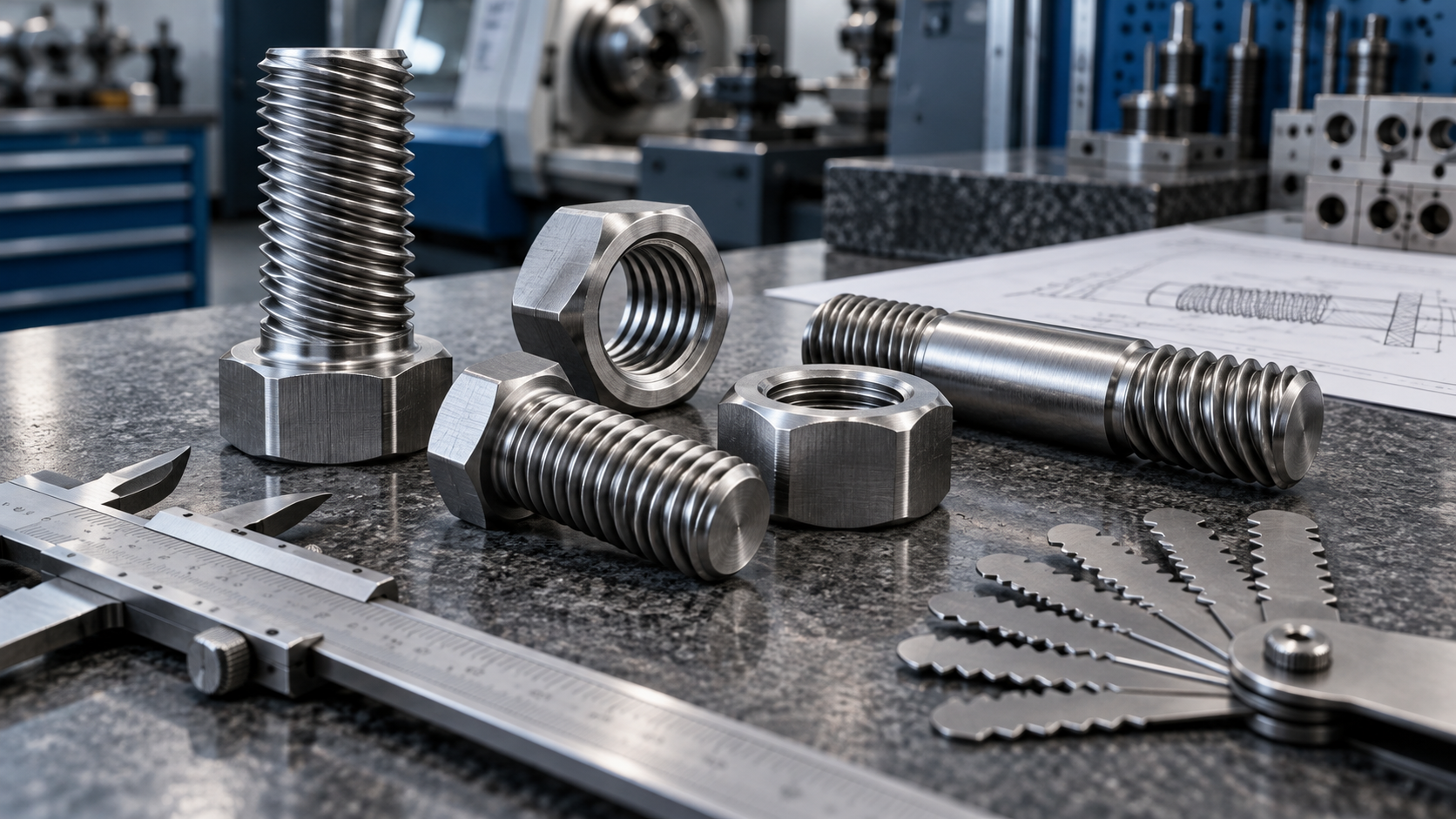
What is a left-hand thread?
A screw thread is a helical ridge wrapped around an external surface, such as a bolt or stud, or cut into an internal surface, such as a nut or tapped hole. “Hand” describes the direction in which that helix advances. Most general-purpose fasteners use a right-hand thread because the common tightening direction is clockwise. A left-hand thread reverses the helix and the tightening direction.
When viewed from the end where the nut is being tightened, a left-hand nut advances along its bolt when it turns counterclockwise. The same relationship applies to a left-hand screw entering a tapped hole. The view matters: if an operator looks from the opposite end of a shaft, the apparent clockwise and counterclockwise directions reverse. The drawing should therefore identify the thread hand and the reference view wherever rotation affects the assembly.
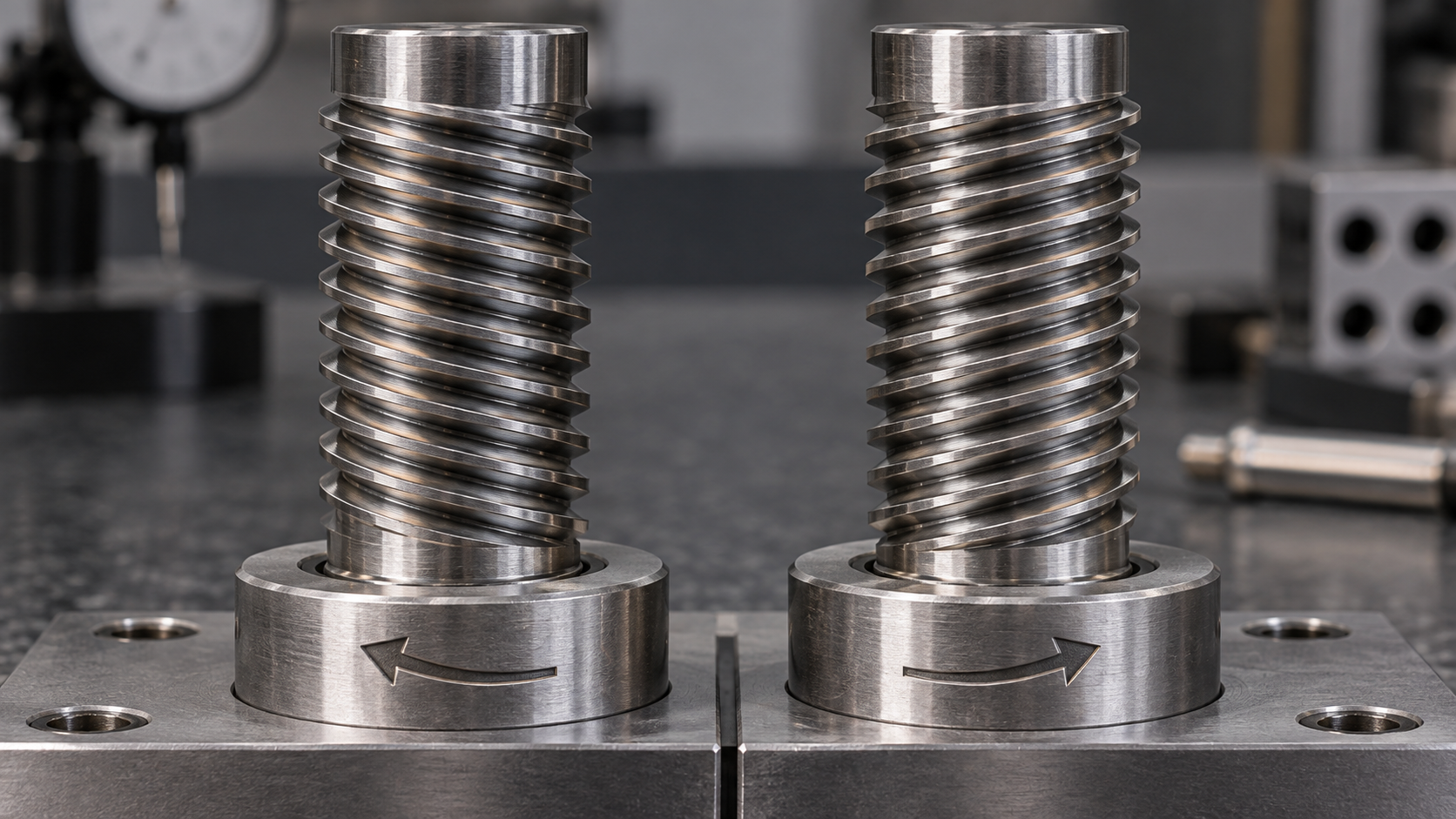
Why do engineers use left-hand threads?
The usual reason is controlled resistance to loosening. If a shaft, drum, wheel, fan, or other component rotates in a direction that applies an unscrewing torque to a right-hand fastener, changing the thread hand can make the operating torque tighten the joint instead. The design decision depends on the actual rotation, the position of the threaded joint, friction, preload, vibration, and the consequences of loosening.
A left-hand thread is not a general substitute for a locking nut, prevailing-torque feature, safety wire, threadlocker, or a correctly designed joint. It changes the screw direction. The joint still needs suitable preload, bearing surfaces, material compatibility, and a maintenance method that prevents a technician from applying force in the wrong direction.
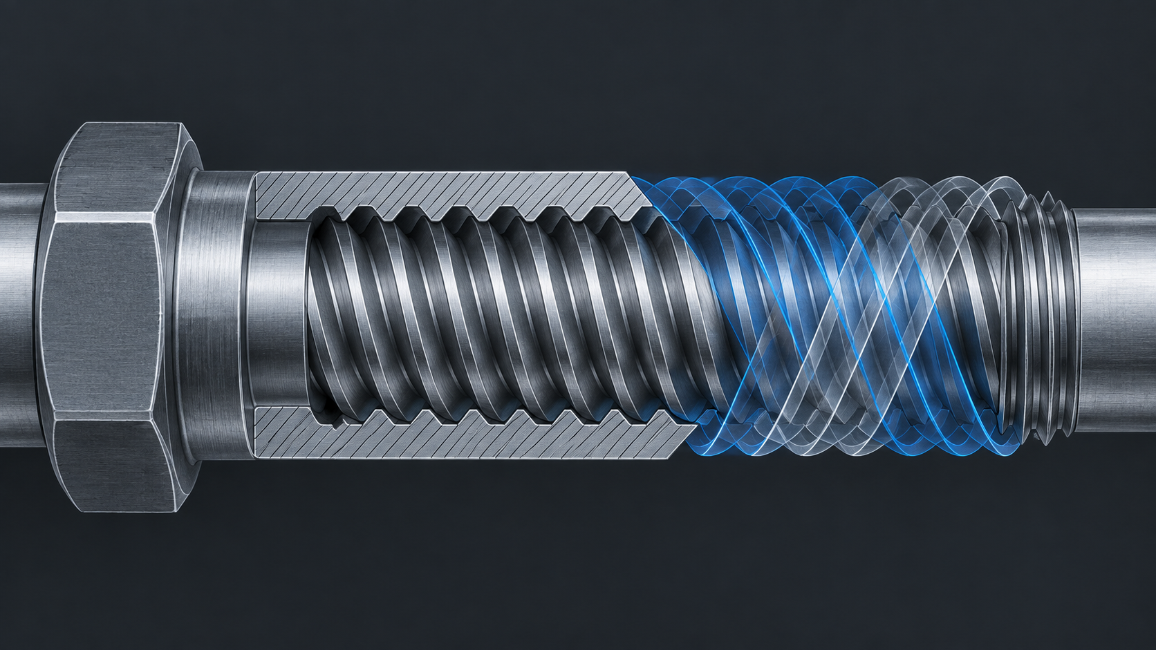
How to tell left-hand and right-hand threads apart
Do not rely on the phrase “lefty loosey” when inspecting an unknown machine. Confirm the thread hand before applying removal torque. A useful field check is to identify the end being tightened, clean enough of the thread to see the helix, and compare its slope with a known reference. If the part or drawing is marked LH or L, treat that marking as a direction warning and verify it against the equipment documentation.
- Set the viewing direction. State which end of the bolt, nut, shaft, or coupling you are facing. Clockwise from one end is counterclockwise from the other.
- Check the helix. A left-hand helix rises in the opposite direction from a conventional right-hand helix when viewed from the side.
- Test engagement by hand. Use the correct mating part and turn gently. A left-hand nut should begin smoothly in the counterclockwise tightening direction. Stop if it binds, rocks, or cross-threads.
- Read the callout. Look for LH, a part-number suffix, a stamped mark, a maintenance note, or a drawing detail. A bare diameter and pitch do not prove the hand.
- Confirm pitch and diameter separately. A correct hand with the wrong pitch can damage the mating thread just as quickly as a wrong hand.
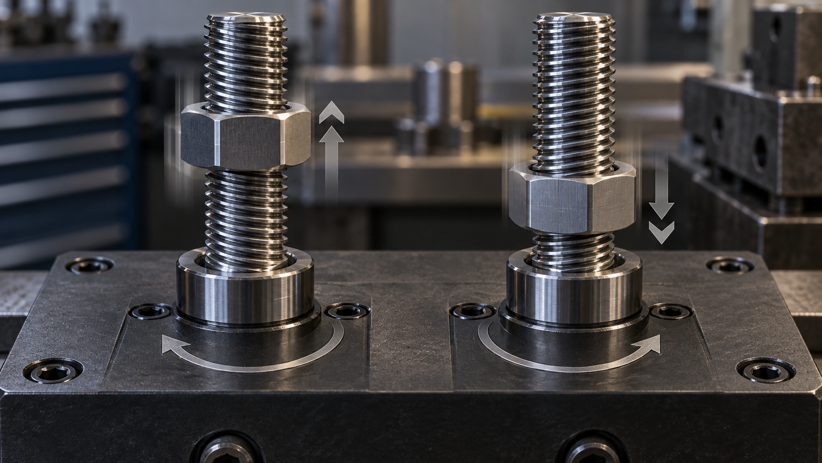
| Check | Right-hand thread | Left-hand thread |
|---|---|---|
| Typical tightening direction | Clockwise when viewed from the tightening end | Counterclockwise when viewed from the tightening end |
| Default assumption | Usually assumed when no LH callout is present | Must be stated on the drawing, specification, or part identification |
| Typical design reason | General fastening and the common tightening convention | Operating torque or motion could loosen the right-hand alternative |
| Compatibility | Use a matching right-hand nut or tapped hole | Use a matching left-hand nut or tapped hole; same size alone is not enough |
Where are left-hand threads used?
Left-hand threads appear where rotation, reciprocating movement, adjustment, or interchange prevention makes the standard direction unsuitable. The exact choice depends on the assembly geometry. A catalog example may show one direction for a particular shaft orientation, while a mirrored machine or a different viewing end can require the opposite direction.
Rotating shafts, drums, and wheels
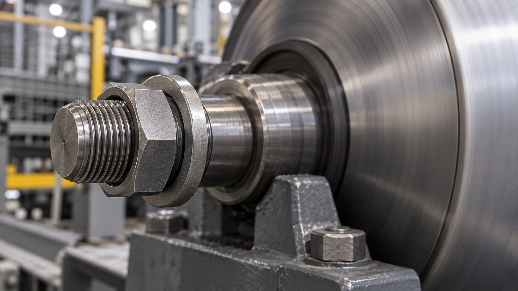
Rotating equipment is the most useful application category for a buyer to investigate. A retaining nut, coupling, rotary joint, or tool attachment can see a torque that tends to unscrew a right-hand thread. McMaster’s rotating-joint data, for example, relates the selected rotating-thread direction to the direction in which a drum turns when viewed from the connecting end. That is the level of detail a drawing should capture: component rotation, observer position, threaded component, and expected service speed.
Paired adjustment and tensioning systems
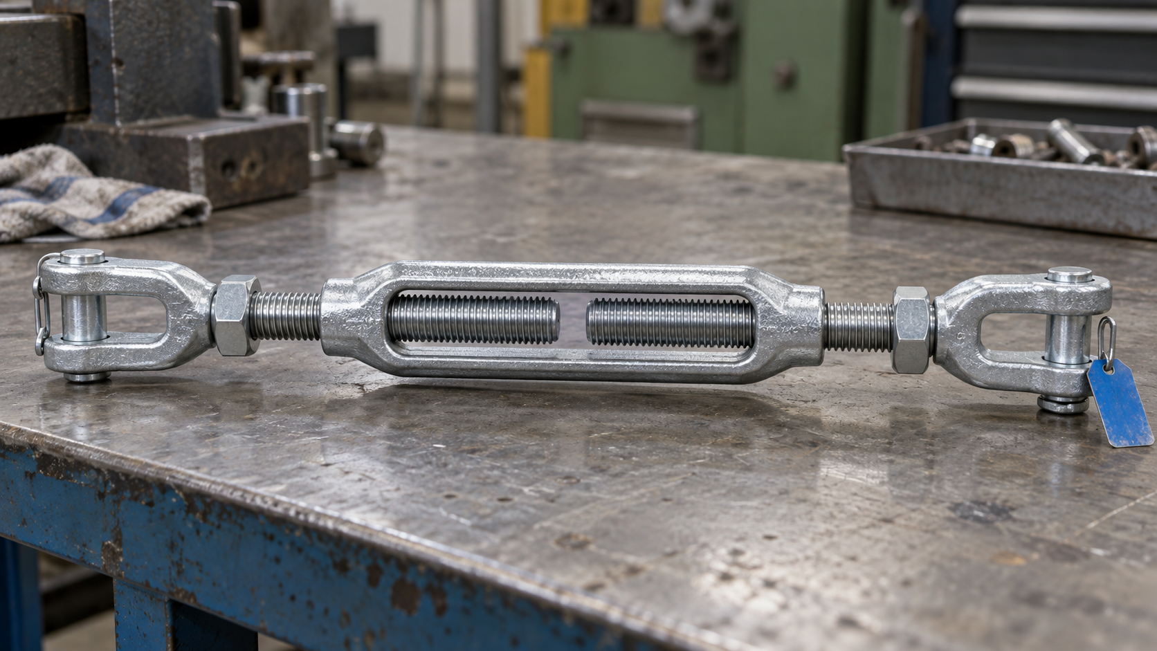
Turnbuckles, rod ends, adjusters, and other paired systems may use a right-hand thread at one end and a left-hand thread at the other. Turning the body can then move both ends in or out without removing the connected parts. The two ends must be identified clearly, because fitting a right-hand nut to the left-hand end will either fail to engage or encourage damaging force.
Special valves, fittings, and replacement parts
Some gas fittings and special valves use thread direction as part of an interchange or connection-control system. This is application-specific: the gas, pressure, jurisdictional code, and valve standard determine the permitted connection. Do not infer a gas-service thread from hand alone. Use the valve manufacturer’s part number, a controlled drawing, or the applicable standard.
Maintenance replacements deserve the same caution. A part may look like a standard bolt while its hand is recorded only in the service manual or on a small mark. Government maintenance guidance for rotating machinery advises checking the hand before loosening and consulting manuals or drawings when the direction is not obvious. If the fastener does not release with the expected torque direction, stop rather than increasing force blindly.
Which fastener forms can use a left-hand thread?
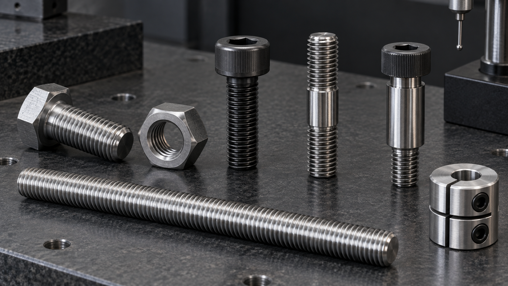
Left-hand thread is a direction option that can be applied to many external and internal forms. The manufacturing route, available tooling, gauge system, size, thread length, and required inspection should be confirmed for the specific part.
| Form | What the buyer should define | Common fit risk |
|---|---|---|
| Left-hand bolt and nut | Head style, across-flats, grip, thread length, nut style, washer, and LH callout | A right-hand replacement has the same outside dimensions but cannot serve the joint |
| Stud | Thread hand at each end, engagement length, unthreaded land, and installation method | One end may intentionally differ from the other in a paired assembly |
| Threaded rod or shaft | Overall length, start, pitch, straightness, end features, and support conditions | A generic rod listing may omit hand, end view, or the mating nut |
| Custom screw or coupling | Complete drawing, load path, torque direction, material, surface finish, and inspection plan | The fastener is treated as a catalog item even though its geometry is application-specific |
How to specify a left-hand threaded fastener
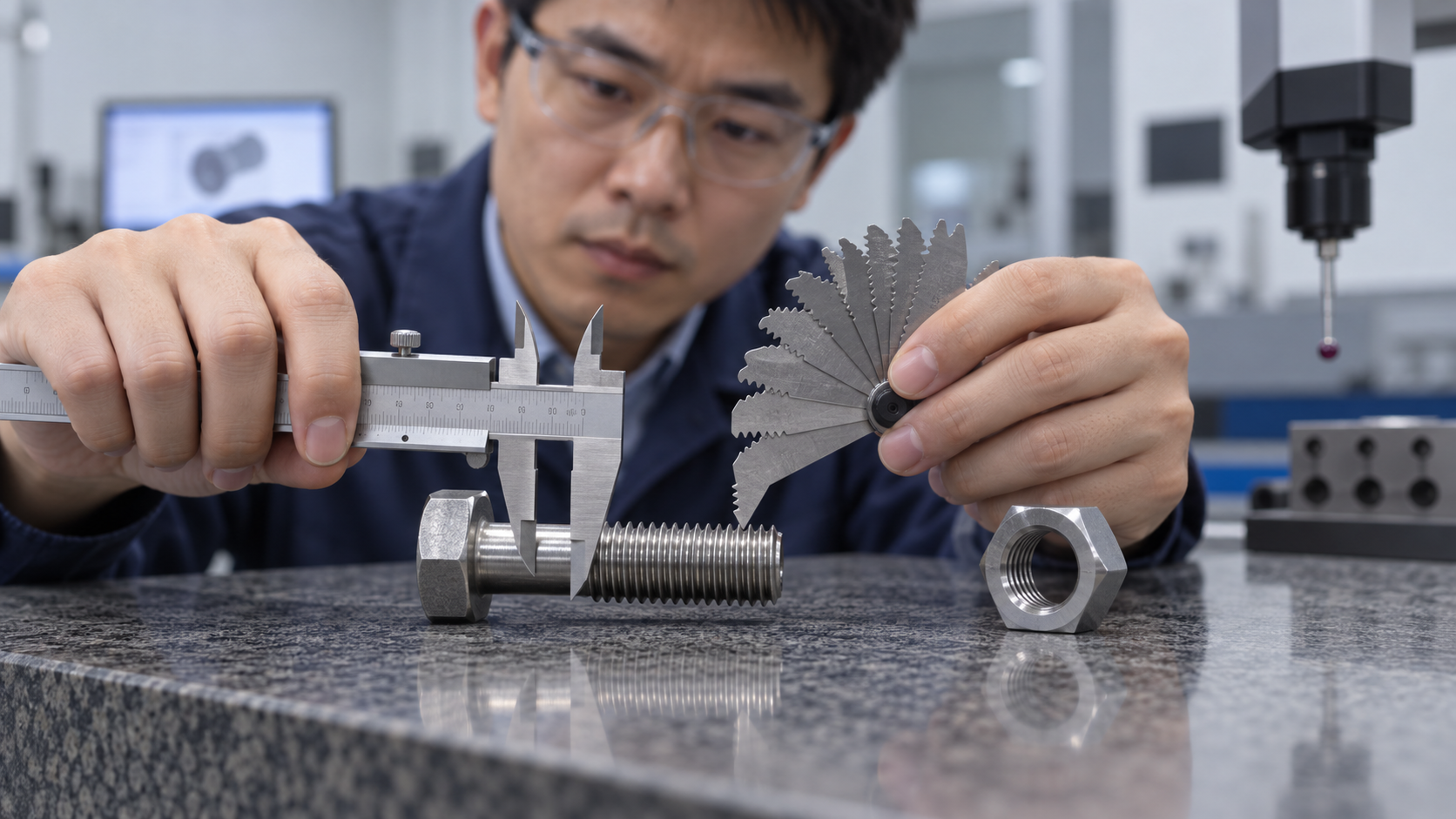
Write the thread hand as one field in a complete callout. A practical metric example could be M12 × 1.5 – 6g LH, while an inch example could be 1/2-13 UNC-2A LH. These examples show the structure of a specification; the correct size, pitch, tolerance class, and standard must come from the design. ASME’s Unified Inch Screw Threads material includes a dedicated method for designating left-hand threads. For metric parts, the supplier should confirm the applicable ISO product and tolerance requirements before production.
- Thread hand: state LH explicitly and show the reference view or rotation direction.
- Thread system: identify metric, UN, UNF, UNC, pipe, Acme, or another defined form. “Left-hand thread” alone is not a thread standard.
- Nominal diameter and pitch: give pitch in millimeters or TPI. Include the lead and number of starts if the thread is multi-start.
- Tolerance or fit class: specify the external and internal classes where the joint requires controlled fit, torque, or interchangeability.
- Fastener geometry: state head, drive, shank, thread length, underhead radius, shoulder, groove, and overall length.
- Material and condition: give the grade, standard, heat-treatment condition, hardness, or mechanical property requirement. Do not use “stainless” or “steel” as the full material callout.
- Finish and lubricant: name coating or plating, thickness limits, friction condition, and the approved assembly lubricant when torque depends on it.
- Mating part: specify the matching left-hand nut, tapped hole, insert, shaft, washer, or coupling and its material.
- Marking and traceability: state whether LH marking, lot identification, material certificates, dimensional reports, or functional gauges are required.

How to match the nut, tapped hole, and thread gauge
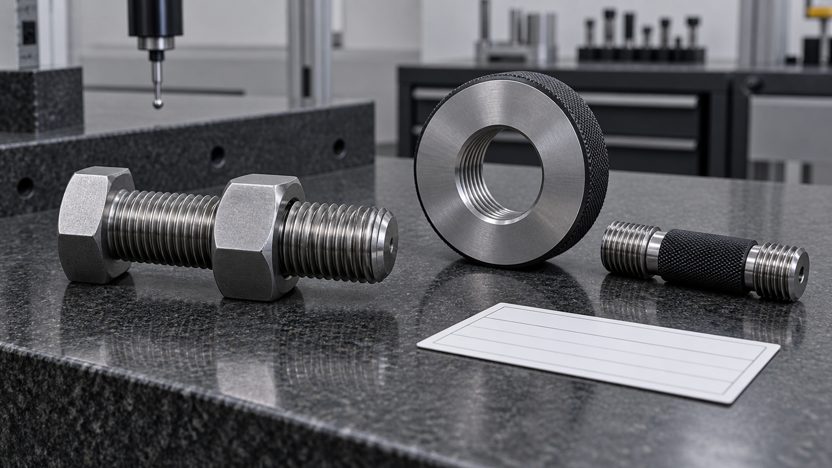
A left-hand external thread only works with a left-hand internal thread of the same nominal size, pitch, form, and compatible tolerance. A nut with the right hand can appear close enough to start by force, especially after paint, dirt, or corrosion has obscured the first threads. That is a reason to clean the part and perform a controlled hand-start check before using a wrench.
For a replacement, record the original fastener and the mating part as a pair. Measure major diameter and pitch or TPI, compare the thread form, inspect the first engaged threads, and check whether the joint uses a special washer, shoulder, or locking feature. If the mating hole is damaged, a new left-hand fastener will not restore the joint by itself; the repair drawing must address the hole and the installation procedure.
Installation and quality controls
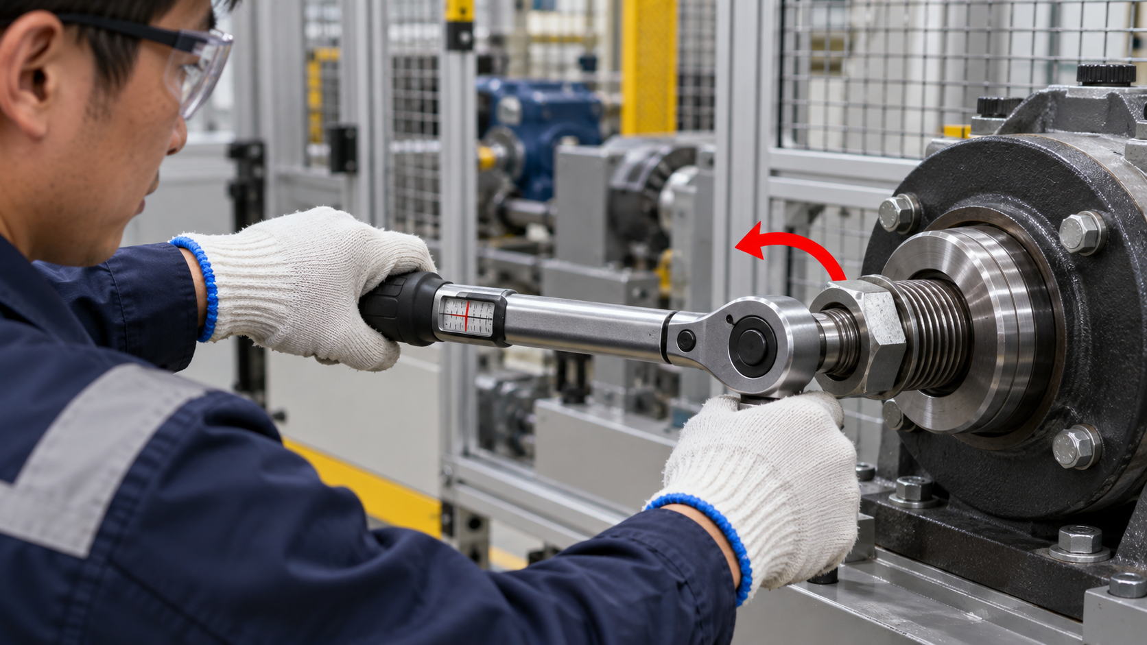
Left-hand threads create a predictable maintenance hazard: a technician who assumes the right-hand convention may tighten a fastener while intending to loosen it. Mark the part, the tool direction, or the work instruction where the risk is material. On rotating equipment, document the shaft direction and the end from which it was determined.
- Clean the joint. Remove burrs, damaged coating, dirt, and corrosion from the mating surfaces and first threads. Keep abrasive particles out of the hole.
- Start by hand. Rotate the nut or screw in the specified tightening direction. It should engage without unusual resistance. Stop at the first sign of cross-threading.
- Control lubrication. Use only the approved lubricant or coating condition. Friction changes can make a familiar torque value produce a different preload.
- Use the correct tool direction. Set the torque wrench for the left-hand tightening direction, confirm how the wrench indicates torque, and keep the operator’s viewing direction in the work instruction.
- Check the result. Inspect seating, exposed thread length, marking, torque record, locking feature, and any required rotation or run-in test.
Galling, damaged threads, or a wrong mating part are not corrected by more torque. Quarantine the parts, compare the drawing and sample, and ask the supplier or responsible engineer to review the joint. For production orders, request dimensional inspection of the thread, a go/no-go functional check when applicable, and material or coating records that match the purchase specification.

Left-hand thread versus reverse thread
In supplier conversations, “reverse thread” is often used as a synonym for left-hand thread. It is useful as a search phrase, but it is not enough for a purchase order. Some users use “reverse” to describe a reverse-rotating tool, a reverse-cutting operation, or a component that moves in the opposite direction. Use left-hand thread (LH) together with the actual thread standard, size, pitch, class, and drawing view.
The design goal also matters. A left-hand fastener can help resist a known operating torque, but it does not automatically solve vibration, fatigue, insufficient preload, poor seating, or material incompatibility. If a joint is safety-critical, have the responsible engineer review the full joint and the maintenance procedure.
Left-hand thread RFQ checklist
Send enough information for a supplier to identify the part without guessing. A drawing is the preferred starting point; a clear sample and application photograph can help with a replacement, but they should be paired with written dimensions and a confirmed thread hand.

- Drawing or dimensioned sketch with the reference viewing end and an explicit LH callout.
- Thread system, nominal diameter, pitch or TPI, tolerance class, thread length, and number of starts.
- Fastener form, head or drive details, shank or shoulder dimensions, and overall length.
- Material grade, heat-treatment condition, hardness or mechanical requirements, and any restricted substitutions.
- Surface treatment, coating thickness, friction condition, lubricant, and corrosion or temperature exposure.
- Mating nut, tapped hole, insert, shaft, washer, or coupling details, including the mating material.
- Rotation direction, service speed, load, vibration, temperature, fluid, and the consequence of loosening.
- Quantity, sample requirement, packaging, marking, lot traceability, certificates, inspection reports, and delivery location.
Send the part drawing, sample measurements, or a photo of the mating assembly through DingLong’s custom fastener inquiry page. Include the LH callout and the rotation direction so the technical review starts with the correct thread hand.
Frequently asked questions
Which way does a left-hand thread tighten?
A left-hand thread tightens counterclockwise and loosens clockwise when viewed from the end where the nut or tool is being tightened. State the viewing end in the drawing because the apparent direction changes when viewed from the opposite end.
What is the purpose of a left-hand thread?
It is used when the motion or torque of the working assembly could loosen a conventional right-hand fastener. The thread direction can make the service torque tighten the joint, but preload, friction, locking features, and the complete joint design still need review.
How can I identify a left-hand threaded bolt?
Look for an LH or L marking, part-number suffix, drawing note, or maintenance instruction, then confirm the helix and test gentle engagement with the correct mating nut. Measure pitch and diameter separately; a matching size does not prove the thread hand.
Can a left-hand thread be metric?
Yes. Metric thread size and pitch are specified in the metric system and the left-hand direction is added as an LH designation, for example M12 × 1.5 – 6g LH. The exact tolerance and product standard should be confirmed for the part.
Do left-hand thread bolts need left-hand nuts?
Yes. The external and internal threads must match in hand, nominal diameter, pitch, form, and compatible tolerance. A right-hand nut is not interchangeable with a left-hand bolt simply because the outside size appears similar.
Are left-hand threads stronger than right-hand threads?
Thread hand alone does not make a fastener stronger. Strength depends on material, diameter, thread geometry, engagement, stress area, heat treatment, preload, and service loading. Select left-hand direction for the torque and motion problem, then specify the required mechanical properties.
Is reverse thread the same as left-hand thread?
Many suppliers use “reverse thread” to mean left-hand thread, but the phrase is less precise. Use the formal LH callout with the thread standard, size, pitch or TPI, tolerance class, and drawing reference so the supplier does not interpret “reverse” as an operating instruction.
Can a fastener manufacturer make left-hand threaded custom parts?
Many special-fastener manufacturers can review left-hand bolts, nuts, studs, rods, shafts, or other machined parts, subject to size, tooling, material, gauge, and quantity. Availability is part-specific. Send the drawing or sample, mating-part information, service rotation, material, finish, quantity, and inspection requirements for confirmation.
Related fastener guides
Technical references
For additional engineering context, see the ASME Unified Inch Screw Threads material, the S9086-CJ-STM-010 fastener maintenance chapter, the Trojan metric thread guide, and the McMaster rotating-joint selection example. These references support thread direction and application checks; they do not replace the drawing, standard, or approval requirements for a particular assembly.