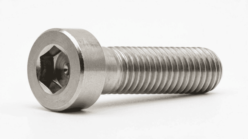
DIN6912 Low Head Socket Cap Screw
DIN6912 is a low-head hex socket cap screw with a central pilot recess, featuring a head height approximately 40% shorter than the standard DIN912, specifically engineered for space-constrained installations where standard head height is not feasible.
When you’re working inside a tight aluminum extrusion channel, mounting a cover plate with only 5 mm of vertical clearance, or assembling a precision fixture where a protruding screw head would interfere with adjacent components — that’s exactly when DIN6912 earns its place. The reduced head profile solves a real engineering problem. But it comes with trade-offs most spec sheets quietly ignore: the pilot recess that prevents wrench slippage also creates an unthreaded zone directly under the head, the strength grade is stamped differently than you’d expect, and there’s a close cousin (DIN7984) that looks nearly identical but behaves differently under the wrench. This guide covers all of it.
What Is DIN6912?
DIN6912 is a low-head hex socket cap screw with a central pilot recess (guide hole), standardized by the German Institute for Standardization (Deutsches Institut für Normung). It belongs to the broader family of socket head cap screws — the same category as the ubiquitous DIN912 / ISO 4762 standard — but with a deliberately reduced head height optimized for applications where vertical clearance is at a premium.
Core Characteristics
Three features define DIN6912 and distinguish it from every other metric socket screw in the market:
1. Reduced head height (k) — The head height is approximately 60% of the equivalent DIN912 dimension. For an M8 screw, DIN912 has a nominal head height of 8 mm; DIN6912 brings that down to 5 mm. That 3 mm difference is trivial in open assemblies but decisive in thin panels, recessed slots, and profile-rail channels.
2. Pilot recess (guide hole) — A central bore passes through the center of the hexagonal socket, continuing partway into the unthreaded shank just below the head. This hole is the defining DIN6912 feature — it exists to accept the guide pin of a DIN6911 key, holding the wrench co-axial with the screw even when the operator can’t see the engagement point directly.
3. Modified strength marking (prefix “0”) — Because the lower head reduces the bending cross-section at the head-to-shank junction, DIN6912 screws cannot carry the same bending load as their DIN912 counterparts of nominally the same grade. The standard resolves this by prefixing the strength grade with zero: 08.8 instead of 8.8, A2-070 instead of A2-70. Tensile strength along the shank axis is unchanged; bending resistance under the head is lower. This prefix is not cosmetic — it is a load-capacity flag that matters in bolted joint design.
Size Range and Tolerance Class
DIN6912 covers thread diameters from M3 to M36, with preferred sizes in the M4–M24 range. Non-preferred sizes (M14, M18, M22, M27) are available but typically require custom orders and longer lead times. All sizes conform to Product Grade A per DIN EN ISO 4759-1, meaning tight dimensional tolerances suitable for precision assemblies.
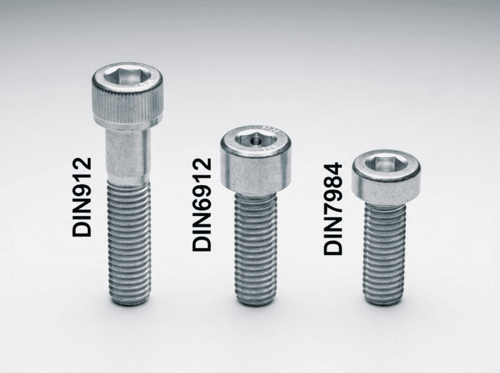
DIN6912 vs DIN912 vs DIN7984: The Key Differences
This is the question that generates the most confusion on purchasing desks and engineering forums alike. Here’s the precise breakdown:
| Comparison Item | DIN912 (Standard Head) | DIN6912 (Low Head + Pilot) | DIN7984 (Low Head, No Pilot) |
|---|---|---|---|
| Head height (k) | Standard height | ~60% of DIN912 | ~60% of DIN912 |
| Pilot recess (center bore) | None | Yes (for DIN6911 wrench) | None |
| Unthreaded zone under head | Minimal | Yes — always present | Minimal |
| Can screw seat flush to workpiece? | Yes | No (unthreaded zone prevents full seating) | Yes |
| Strength grade marking | 8.8 / 10.9 / A2-70 | 08.8 / A2-070 (prefixed with 0) | 8.8 / A2-70 |
| Anti-slip wrench system | Standard hex key only | DIN6911 guided hex key | Standard hex key only |
| Typical application | General high-strength connections | Tight clearance + wrench anti-slip | Tight clearance + flush seating needed |
The practical decision rule: if you need flush seating under the head, choose DIN7984. If you need anti-slip wrench control in blind or cramped locations, choose DIN6912. If head height is not constrained, DIN912 gives you the highest bending capacity.
According to the DIN standards body, DIN6912 was developed specifically to address industrial assembly scenarios where neither the operator’s line of sight nor available tool swing angle is sufficient to safely drive a standard socket screw without risking cam-out damage.
Engineering tip: Specifying DIN6912 “for tighter torque control” without actually needing the reduced head height is counterproductive — you surrender bending capacity and full seating for no gain. Use it only when the geometry genuinely demands it.
DIN6912 Complete Dimension Table (M3–M36)
The table below covers all standard and non-preferred sizes. Values represent nominal dimensions in millimeters per DIN6912:2011. Non-preferred sizes are marked with parentheses.
| Thread (d) | Pitch P (mm) | Head Ø dk (mm) | Head Height k (mm) | Hex Socket s (mm) | Key Depth t1 (mm) | Thread Length b (mm) |
|---|---|---|---|---|---|---|
| M3 | 0.5 | 5.5 | 2.0 | 2 | 1.5 | 12 |
| M4 | 0.7 | 7 | 2.8 | 3 | 1.6 | 14 |
| M5 | 0.8 | 8.5 | 3.5 | 4 | 2.0 | 16 |
| M6 | 1.0 | 10 | 4.0 | 5 | 2.5 | 18 |
| M8 | 1.25 | 13 | 5.0 | 6 | 3.0 | 22 |
| M10 | 1.5 | 16 | 6.5 | 8 | 3.5 | 26 |
| M12 | 1.75 | 18 | 7.5 | 10 | 4.0 | 30 |
| (M14) | 2.0 | 21 | 8.5 | 12 | 4.5 | 34 |
| M16 | 2.0 | 24 | 10.0 | 14 | 5.5 | 38 |
| (M18) | 2.5 | 27 | 11.0 | 14 | 6.0 | 42 |
| M20 | 2.5 | 30 | 12.0 | 17 | 6.5 | 46 |
| (M22) | 2.5 | 33 | 13.0 | 17 | 7.0 | 50 |
| M24 | 3.0 | 36 | 14.0 | 19 | 7.0 | 54 |
| (M27) | 3.0 | 40 | 15.5 | 19 | 7.5 | 60 |
| M30 | 3.5 | 45 | 17.5 | 22 | 8.0 | 66 |
| M36 | 4.0 | 54 | 21.5 | 27 | — | 78 |
Dimension key:
dk = head outside diameter
- k = head height
- s = hex socket across-flats dimension
- t1 = hex socket engagement depth
- b = thread length (from point to underside of head)
Important notes on the table:
- Sizes in parentheses (M14, M18, M22, M27) are non-preferred — available from most stocking distributors in carbon steel 08.8, but stainless grades typically require custom orders with 4–8 week lead times.
- M30 and M36 are large-format sizes not held in standard inventory by most distributors; verify availability and confirm dimensions against current supplier drawings before specifying.
- Full-thread (fully threaded) variants exist for shorter bolt lengths. However, due to the pilot recess extending into the shank, there will always be a short unthreaded zone directly under the head — even on “full thread” DIN6912 screws.
Materials and Strength Grades
DIN6912 screws are manufactured in three main material families. The strength grade marking follows a modified convention — always with the “0” prefix — to distinguish the reduced bending capacity from standard-head equivalents.
| Material | DIN6912 Grade Marking | Tensile Strength (Rm) | Typical Application |
|---|---|---|---|
| Carbon steel (medium alloy) | 08.8 | 800 N/mm² | General machinery, jigs, structural panels |
| Carbon steel (high-strength alloy) | 010.9 | 1040 N/mm² | High-load structural connections in tight-space enclosures |
| Stainless steel 304 (A2) | A2-070 | 700 N/mm² | Food processing, marine, corrosive environments |
| Stainless steel 316 (A4) | A4-070 | 700 N/mm² | Offshore, chemical processing, high-chloride exposure |
| Stainless steel 316 high-strength (A4) | A4-080 | 800 N/mm² | Demanding marine/chemical with higher torque requirement |
Surface treatments available for carbon steel grades:
- Plain (bright) — as-machined, no coating; use in dry indoor assemblies
- Black oxide (phosphate) — mild corrosion resistance, common in machinery
- Zinc electroplated (white zinc) — moderate outdoor corrosion resistance
- Dacromet / Geomet — high corrosion resistance (≥ 480 h salt spray), preferred for automotive and outdoor structural use
The “0” prefix matters in joint design. When calculating head pull-through loads or bending moments at the shank/head junction, use the DIN6912-specific load tables — do not substitute DIN912 08.8 data for DIN912 8.8 data, or you will overestimate the head’s bending resistance by approximately 30–40%.
DIN6912 Application Scenarios
DIN6912’s combination of low head profile and pilot-recess anti-slip system makes it the right choice in six recurring industrial scenarios:
DIN6912 — Selection Guide
1. Mechanical panel and cover plate fastening — When a hinged cover, inspection plate, or access door sits in a recessed pocket and only 4–6 mm of head clearance exists above the workpiece surface, standard DIN912 heads physically cannot fit. DIN6912 solves the geometry without resorting to countersunk heads (which require a conical counterbore and reduce pullout resistance).
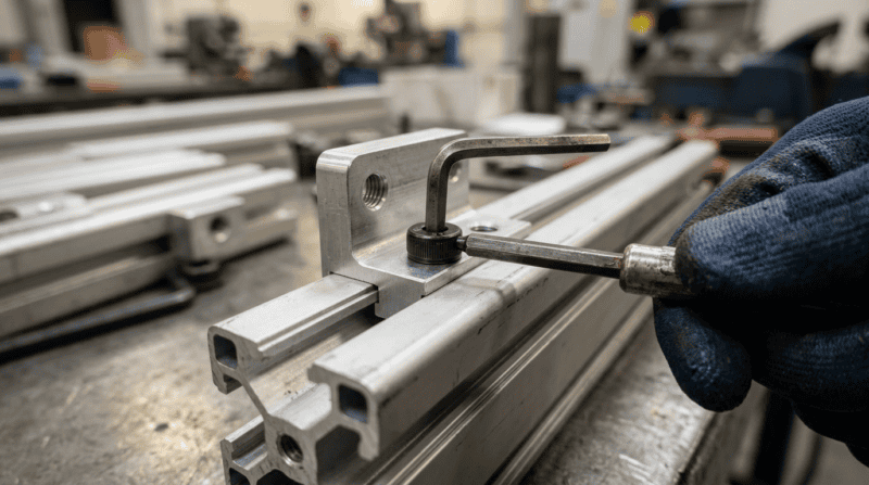
2. Aluminum T-slot extrusion assembly — The 20-series and 40-series T-slot aluminum profiles used extensively in machine frames, conveyor systems, and automation cells have slot widths and depths optimized for low-head fasteners. DIN6912 M5 and M6 are the most common choices for this application.
3. Thin-walled component fastening — Sheet metal enclosures, electronics housings, and thin-section castings where a protruding standard head would create clearance or aesthetic problems. The low k dimension keeps the head below or flush with surrounding surfaces.
4. Precision jigs and fixtures — Tooling and fixture assemblies that get assembled and disassembled frequently in workshops where the operator works by feel rather than by sight. The DIN6911 guided key locks into the pilot recess and prevents the wrench from drifting off-axis during insertion torquing, protecting both the hex socket and the surrounding workpiece surface.
5. Electronics and instrument enclosure assembly — Compact devices where internal real estate is tight and screw heads that stand proud of circuit boards or brackets would conflict with neighboring components. Low-head socket screws — including DIN6912 — are standard in instrument-grade assemblies.
6. Automated assembly systems — In robotic screwdriving applications where the driver bit must enter through a restricted aperture, the reduced head height directly reduces the minimum aperture diameter required for access, enabling tighter product packaging.
The Pilot Recess: How It Works and When It Matters
The pilot recess (Führungsbohrung in German; sometimes called a guide hole or centre bore) is DIN6912’s most misunderstood feature. Most catalogues mention it exists; very few explain what it actually does in practice.
The mechanism: A DIN6911 T-handle or L-key has a cylindrical guide pin protruding from the tip of the hex blade. When the key is inserted into a DIN6912 screw, the hex engages the socket drive and the guide pin seats inside the pilot bore — mechanically constraining the wrench’s axis to align with the screw’s axis. In a confined space where you can’t see the engagement or steady the wrench visually, this prevents the 5–10° angular misalignment that causes cam-out (rounding the socket corners) or screw head damage.
Where it creates a constraint: The pilot bore extends from the hex socket down through the head and into the shank. This means the thread cannot extend all the way to the underside of the head. There is always a smooth (unthreaded) cylindrical zone beneath the head, typically 1–3 mm long depending on size. This unthreaded zone has two consequences:
- DIN6912 cannot fully seat flush — The underside of the head will not contact the workpiece until the unthreaded zone has passed below the top surface. If your design requires the screw head to pull directly down on a surface for clamping, and the thread engagement reaches the surface before the head lands, you get reduced clamping effect. In this case, DIN7984 is the correct choice.
- Minimum hole depth requirement — Threaded blind holes for DIN6912 must be deep enough to accommodate both the required thread engagement length AND the unthreaded zone. Under-depth holes will strip before achieving target torque.
According to Wikipedia’s overview of socket head cap screws, the cam-out failure mode in confined-space assembly is one of the most common sources of fastener head damage in precision manufacturing — exactly the failure mode DIN6912’s pilot recess is engineered to prevent.
Selection Guide: When to Specify DIN6912
The decision is not complicated once the geometry is established. Work through this in sequence:
Step 1 — Is head height constrained
Measure the available vertical clearance above the workpiece surface at the fastener location. Compare it against the DIN912 head height (k) for your thread size.
- If clearance ≥ DIN912 k: use DIN912. You gain full bending capacity and no unthreaded-zone complications.
- If clearance < DIN912 k: proceed to Step 2.
Step 2 — Is wrench anti-slip control needed
Consider whether the assembly position allows the operator (or robot) to visually confirm hex key alignment, and whether there’s sufficient lateral stability to prevent angular drift during torquing.
- If assembly is blind (cannot see engagement), cramped (no room to steady the key), or involves operators working in awkward positions: use DIN6912 with a DIN6911 guided key.
- If operator can see and steady the wrench normally: proceed to Step 3.
Step 3 — Is flush head seating required
Does the design require the underside of the screw head to make full contact with the workpiece surface for clamping, sealing, or aesthetic reasons?
- If yes: use DIN7984 (low head, no pilot recess, full seating possible).
- If no: DIN6912 or DIN7984 are both viable. DIN6912 adds anti-slip protection at no significant cost premium; DIN7984 avoids the unthreaded-zone complication if hole depth is borderline
Common specification mistakes to avoid:
- Ordering DIN6912 in 08.8 when the joint design assumed 8.8 capacity — these are not equivalent under bending load at the head.
- Specifying M30 or M36 DIN6912 without confirming stock availability — lead times of 8–16 weeks are common for large-format low-head socket screws.
- Using a standard L-key hex wrench in DIN6912 screws in confined spaces — functional, but defeats the purpose of the pilot recess. Invest in a DIN6911 key set for production environments.
For broader context on metric fastener selection methodology, Bossard’s fastener engineering guide provides solid background on joint design with reduced-head fasteners.
How to Write a DIN6912 Purchase Order
The standard procurement notation follows the DIN fastener naming convention:
Screw DIN6912 – M8 × 25 – 08.8
Breaking this down:
- DIN6912 — the standard designation (specifies head geometry, pilot recess, tolerance class)
- M8 — nominal thread diameter in mm
- 25 — nominal length in mm, measured as total screw length including the head (this differs from some other standards — always confirm with your supplier for non-standard sizes)
- 08.8 — strength grade (note the “0” prefix — ordering “8.8” by mistake will get you DIN912 screws from some suppliers)
For stainless variants: Screw DIN6912 – M6 × 20 – A2-070
When placing bulk orders (typically 500+ pieces), also specify:
- Surface treatment (plain / black oxide / zinc white / Dacromet)
- Whether a material test certificate (EN 10204 3.1 or 3.2) is required
- Whether third-party inspection is needed
- Packaging requirements (bulk bag vs. box-counted)
Suppliers in the EU and Asia typically stock preferred sizes (M4–M24) in 08.8 and A2-070 as standard inventory. For non-preferred sizes, specialty grades (010.9, A4-080), or surface treatments beyond plain and zinc, confirm availability and minimum order quantities before releasing engineering drawings.
Frequently Asked Questions
Q1: What is the difference between DIN6912 and DIN912?
DIN6912 has a head height approximately 40% lower than DIN912 and includes a central pilot recess for use with a DIN6911 guided hex key. DIN912 has a full-height head, higher bending resistance at the head, and no guide bore — making it the choice for general-purpose high-strength connections where head clearance is not a constraint. The strength grade notation also differs: DIN6912 uses 08.8 and A2-070 (with a zero prefix) to indicate reduced head bending capacity, while DIN912 uses 8.8 and A2-70.
Q2: Why does DIN6912 use 08.8 instead of 8.8 for strength grade?
The “0” prefix indicates that while the tensile strength of the shank is equivalent to an 8.8 screw, the bending resistance at the head-to-shank junction is lower due to the reduced head height. DIN6912 screws cannot sustain the same bending moment under the head as their DIN912 counterparts. The prefix prevents designers from directly substituting DIN6912 into joint calculations written for DIN912 8.8 — doing so would overestimate the head’s structural contribution.
Q3: Can DIN6912 screw heads sit fully flush against a workpiece surface?
No. Because the pilot recess extends through the head and into the shank, there is always a short unthreaded section below the head. This means the head cannot pull down to full contact with the workpiece surface until the unthreaded zone has cleared the surface — which in a properly dimensioned through-hole assembly means a small gap always remains. If flush head-to-surface contact is required (for clamping, sealing, or appearance), specify DIN7984 instead.
Q4: What tool does DIN6912 require?
DIN6912 is designed to work with DIN6911 hex keys, which have a cylindrical guide pin at the tip that seats in the pilot bore and keeps the wrench co-axial with the screw. Standard hex (Allen) keys also work — but in confined spaces where visual alignment is difficult, they risk the angular drift that causes socket cam-out and head damage. For production environments and frequent assembly cycles, a DIN6911 key set is the correct investment.
Q5: What information is needed to order DIN6912 screws in bulk?
To place an accurate bulk order, provide: nominal size (e.g., M8×25), strength grade (e.g., 08.8 or A2-070), surface treatment (plain, black oxide, zinc, Dacromet), quantity, packaging preference (bulk vs. counted box), and whether material certificates or third-party inspection reports are required. For non-preferred sizes or specialty grades, also confirm stock availability and minimum order quantity with the supplier before releasing the specification to purchasing.
Conclusion
DIN6912 is not a substitute for DIN912 — it’s a precision tool for a specific engineering problem. When vertical clearance drops below the DIN912 head height, and when working conditions make wrench alignment unreliable, DIN6912’s low profile and pilot recess combination solves both issues simultaneously.
The key details to lock in before specifying: confirm the unthreaded zone under the head won’t conflict with your hole depth or clamping requirement (if it does, switch to DIN7984); use the correct 08.8 / A2-070 grade marking in your purchase orders; and pair the screws with DIN6911 guided keys to actually leverage the pilot recess advantage. Get those three right, and DIN6912 will perform exactly as the standard intends.
For sourcing, contact us directly with your size, grade, surface finish, and quantity requirements — we stock preferred sizes M4 through M24 in 08.8 and A2-070 for same-week dispatch.