
 English
  German
  Spanish
  Portuguese
  French
  Japanese
  Arabic
  Korean
  Vietnamese
  Russian
 DIN 6912 Low Head Socket Cap Screws, M4-M36
DIN 6912 low head socket cap screws are specified when a full-height socket head does not fit the assembly. DIN 6912:2021-03 covers M4 to M36 screws with a centre guide recess, product grade A, and steel or stainless-steel materials. The recess accepts a guided DIN 6911 hex key and helps keep the driver aligned in a blind or cramped position. The lower head also means reduced loadability compared with standard-head designs, so the screw should not be selected only from its diameter and length. Check head clearance, hole depth, the short unthreaded shank under the head, required material or property class, finish, and inspection documents before releasing a drawing. DingLong can review the selected size, length, grade, surface treatment, quantity and packaging requirements before preparing a quotation.
This page is written for engineers, procurement teams and distributors who need to compare a low-head geometry with a standard socket cap screw. Use the dimension table as a screening reference, then release the exact part against the current standard, buyer drawing and quotation confirmation.
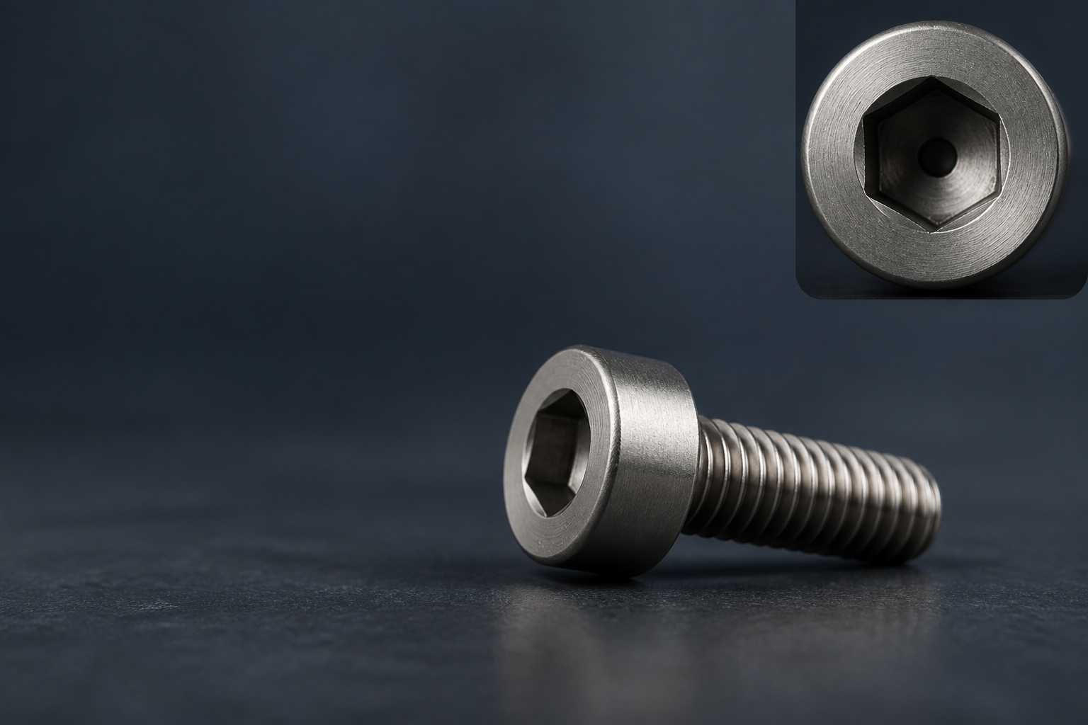
Illustrative product visual. Confirm dimensions, finish and documentation against the quotation drawing.
Current standard
DIN 6912:2021-03
Thread scope
M4 to M36
Drive feature
Centre guide recess
Material scope
Steel and stainless steel
What DIN 6912 changes in the joint
DIN 6912 is the low-head, centre-guided member of the metric socket screw family. The current standard names the resulting limitation directly: the head geometry creates reduced loadability. That wording matters during joint design. A smaller head may solve a clearance problem, but a DIN 6912 screw should not inherit a full-height DIN 912 load assumption without checking the applicable data.
The centre feature also affects the shank. DIN 6912 screws require a short unthreaded portion below the head to make room for the guide feature. Check that portion against the hole depth, clamping surface and assembly sequence before approving the part. A part can have the correct nominal diameter and still be unsuitable if the head seats against the wrong surface or the threaded section starts too early for the joint.
For procurement, the standard name is therefore only the first line of the specification. The part number should be tied to the diameter, pitch, length, material or property class, finish, tolerance and inspection documents required by the assembly. If any of those fields are open, send the drawing or mating-hole information before a production quotation is finalized.
Engineering note: The standard scope and the supplier’s drawing control the final specification. Use the table below for a first selection, then confirm the exact length, tolerance, material or property class and inspection requirement with the quotation drawing. DIN 6912 is a clearance-led design choice, not a universal replacement for DIN 912.
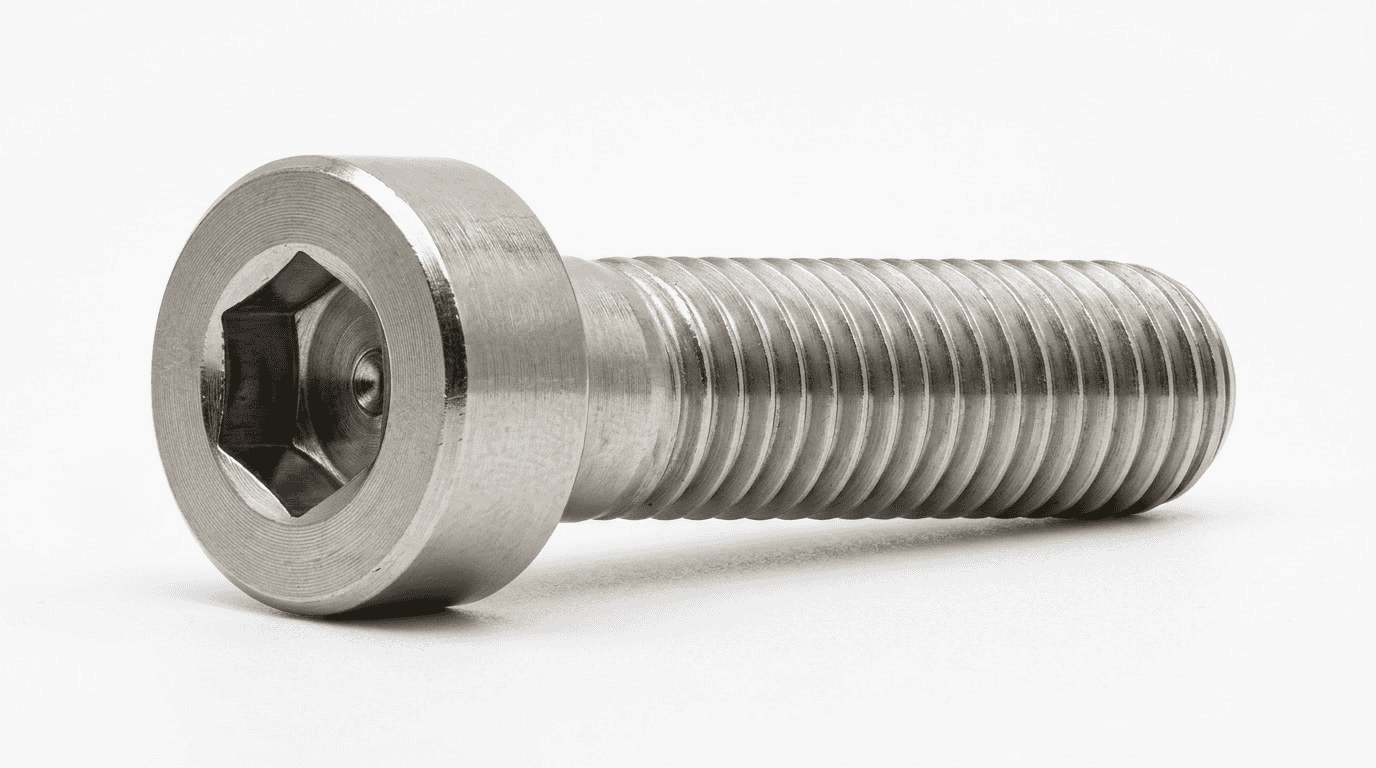
Low head geometry with a centre guide feature. Use the product image for orientation only, not as a dimensional reference.
How the centre guide changes assembly
The centre guide recess changes both the tool interface and the assembly review. It is intended to work with a guided DIN 6911 hex key, so the driver can be kept more accurately in line with the screw axis when access is blind, recessed or close to an adjacent wall. That can be useful in compact fixtures, covers and profile-based assemblies where the operator has limited visibility.
The guide feature does not replace a torque procedure, a joint calculation or a seating check. Confirm the key size, driver clearance and usable engagement for the selected diameter. The driver must still reach the socket completely and the head must seat on the specified bearing surface without interference.
Review these four points
- Tool pairing: confirm whether the assembly uses a guided DIN 6911 key or another approved driver.
- Entry direction: check whether the tool can approach the screw in a straight, repeatable line.
- Seating: verify that the low head does not contact a cover, rail or adjacent component before the joint is clamped.
- Service access: consider whether a future removal tool can reach the screw after the surrounding parts are installed.
Assembly review checklist
Useful on a buyer drawing
- Socket and guide feature called out by the applicable standard.
- Head clearance shown from the bearing face to the nearest obstruction.
- Hole depth and thread engagement shown for the selected length.
- Approved driver or DIN 6911 key size identified.
- Seating face, washer condition or counterbore requirement stated.
See a supplier reference for the low-head, pilot-recess concept, then confirm the production drawing for the actual order.
DIN 6912 vs DIN 912 vs DIN 7984
Choose by geometry, driver access and load case. A low head alone does not identify the right socket screw.
| Selection point | DIN 912 / ISO 4762 | DIN 6912 | DIN 7984 |
|---|---|---|---|
| Head form | Full-height cylindrical socket head | Low head with centre guide recess | Low head without the DIN 6912 centre feature |
| Primary reason to specify | Head clearance is available and the standard full-height design fits | Head height is constrained and guided driver alignment is useful | Head height is constrained and a standard socket driver is preferred |
| Tooling consideration | Standard hex key or driver | DIN 6911 guided hex key is the relevant pairing | Standard hex key or driver |
| Load note | Use the applicable full-height standard data | DIN 6912:2021-03 identifies reduced loadability from the head geometry | Check the current standard and product data before substituting |
| Buyer check | Confirm diameter, length, grade and finish | Confirm guide feature, unthreaded shank, load case and driver access | Confirm head profile, seating condition, size and driver access |
DIN 6912 dimension reference, M4-M36
The reference table below includes preferred and non-preferred diameters published for the current M4 to M36 scope. Use the drawing revision and the selected length to confirm the final part.
| Thread d | Pitch P | Head diameter dk max | Head height k max | Socket s nominal | Guide depth t1 nominal | Thread length b for l <= 125 |
|---|---|---|---|---|---|---|
| M4 | 0.7 | 7 | 2.8 | 3 | 1.6 | 14 |
| M5 | 0.8 | 8.5 | 3.5 | 4 | 2 | 16 |
| M6 | 1.0 | 10 | 4.0 | 5 | 2.5 | 18 |
| M8 | 1.25 | 13 | 5.0 | 6 | 3 | 22 |
| M10 | 1.5 | 16 | 6.5 | 8 | 3.5 | 26 |
| M12 | 1.75 | 18 | 7.5 | 10 | 4 | 30 |
| (M14) | 2 | 21 | 8.5 | 12 | 4.5 | 34 |
| M16 | 2 | 24 | 10 | 14 | 5.5 | 38 |
| (M18) | 2.5 | 27 | 11 | 14 | 6 | 42 |
| M20 | 2.5 | 30 | 12 | 17 | 6.5 | 46 |
| (M22) | 2.5 | 33 | 13 | 17 | 7 | 50 |
| M24 | 3 | 36 | 14 | 19 | 7 | 54 |
| (M27) | 3 | 40 | 16 | 19 | 8.5 | 60 |
| M30 | 3.5 | 45 | 17.5 | 22 | 9 | 66 |
| (M33) | 3.5 | 50 | 19.5 | 24 | 10 | 72 |
| M36 | 4 | 54 | 21.5 | 27 | 11.5 | 78 |
Dimensions are nominal reference values in millimeters. Parentheses indicate non-preferred sizes in commonly published DIN 6912 tables. The current standard scope is M4 to M36. Confirm the applicable length range, thread length, tolerance and drawing revision before production release.
Check the current DIN 6912 standard record and send the selected drawing to DingLong for a supply review.
How to read the DIN 6912 drawing
The symbols below are the fields buyers most often need when comparing a standard table with a supplier drawing. They should be read together, because head clearance, socket depth and thread length determine whether the screw works in the complete joint.
| Drawing field | What it describes | Why it matters to the buyer |
|---|---|---|
| d / P | Nominal thread diameter and pitch | Controls the mating thread, tap size and the available length series. |
| dk | Maximum head diameter | Controls radial clearance around the screw head and the required counterbore or recess. |
| k | Maximum low-head height | Controls the clearance envelope above the bearing surface. |
| s | Nominal hex socket size | Controls the driver or key selection and the usable torque interface. |
| t1 / t2 | Guide and socket-related depths | Must be read with the selected tool and the current drawing revision. |
| b | Thread length for the applicable screw-length class | Determines how much thread enters the mating part and where the unthreaded shank begins. |
Thread length reference by screw length class
The following reference helps compare the threaded portion for common length classes. Values are in millimeters and must be checked against the current standard and the final drawing.
| Thread d | b for l <= 125 | b for 125 < l <= 200 | b for l > 200 |
|---|---|---|---|
| M4 | 14 | 20 | – |
| M5 | 16 | 22 | – |
| M6 | 18 | 24 | – |
| M8 | 22 | 28 | – |
| M10 | 26 | 32 | – |
| M12 | 30 | 36 | – |
| M14 | 34 | 40 | – |
| M16 | 38 | 44 | 57 |
| M18 | 42 | 48 | 61 |
| M20 | 46 | 52 | 65 |
| M22 | 50 | 56 | 69 |
| M24 | 54 | 60 | 73 |
| M27 | 60 | 66 | 79 |
| M30 | 66 | 72 | 85 |
| M33 | 72 | 78 | 91 |
| M36 | 78 | 84 | 97 |
The thread-length values above are a published reference for the common length classes, in millimeters. They help screen thread engagement but do not replace the final drawing. Check whether the selected length is enough for the joint, whether the unthreaded portion enters a clearance hole, and whether the screw reaches the bottom of a blind tapped hole.
For a blind hole, allow room for the drill point, chips and the end of the screw. For a through-hole with a nut or tapped plate, confirm that the threaded section reaches the intended load-bearing engagement without bottoming against a shoulder. The correct length is a function of the joint stack-up, not a fixed percentage of the nominal diameter.
Materials, grades and finishes
DIN 6912:2021-03 covers screws made of steel and stainless steel. The property class, stainless grade, finish and documentation are quotation fields for the exact part. Do not treat a general material family as proof that every grade or coating is available from stock.
- Material: carbon or alloy steel, or stainless steel as required by the drawing and service environment.
- Property class or stainless designation: specify the exact value and the applicable calculation basis. A diameter alone does not define the load capability of the finished part.
- Finish: state the surface condition or coating requirement, including any restricted-substance, dimensional or corrosion-test document.
- Documentation: request the material report, dimensional inspection record or third-party inspection only when it is required for the order.
When corrosion exposure, temperature, electrical contact or cleanliness is important, describe the environment in the RFQ. That allows the material and finish review to follow the actual application instead of relying on a generic “stainless” or “coated” label.
What to include in your RFQ
Send these details with the inquiry so the quotation is based on the real joint:
- Geometry: thread size, pitch and nominal length, for example M8 x 25.
- Material: property class, stainless designation or the material callout from the drawing.
- Surface: plain finish, coating system, color or restricted-substance requirement.
- Order: quantity by size and length, split delivery needs and packaging preference.
- Quality: drawing tolerance, first-article requirement, material certificate, dimensional report or inspection level.
- Assembly: mating material, blind or through-hole, required driver, seating face and any clearance limit.
For a non-preferred diameter, unusual length or special finish, attach the drawing before purchasing confirms the part number. If the screw is used in a safety-related or highly loaded joint, include the calculation basis or acceptance standard needed by your quality team.
Material and documentation matrix
| Material route | Specify in the RFQ | Confirm before production |
|---|---|---|
| Steel | Property class, base material, finish and service environment | Material report, finish or coating record, dimensional inspection |
| Stainless steel | Exact stainless designation, finish and corrosion environment | Material certificate, surface condition and any special test requirement |
| Special finish | Coating system, thickness or dimensional restriction, color and compliance note | Coating evidence, thread and head inspection after treatment |
Availability of a particular grade, finish or document package must be confirmed for the quotation. This table is a buyer-side specification guide, not a stock list.
A practical DIN 6912 selection path
DIN 6912 is a geometry-led selection. Work through these checks before choosing a part number.
Check head clearance
Measure the available space above the joint. If a full-height DIN 912 head fits without interference, it may remain the simpler choice. If the head height is the constraint, compare the low-head alternatives.
Check driver alignment
Decide whether the driver enters a blind or cramped position. The centre guide feature is relevant when a guided DIN 6911 key can improve alignment during assembly.
Check the load path
Check the load path, the short unthreaded shank and the required seating condition. Because DIN 6912 has reduced loadability from its head geometry, the joint calculation must use the appropriate data.
Know when to pause the substitution. If the joint depends on high preload, repeated tightening, impact, fatigue or a very small bearing area, ask for a drawing review before replacing a full-height screw. If the head-height problem is the only constraint, compare the low-head options by guide feature, socket access and load data rather than by product name alone.

Illustrative application context. Confirm the real assembly clearance, hole depth and required load data from the buyer drawing.
Where the low head and guide matter
DIN 6912 becomes relevant when the joint has a real space or tool-access constraint. Common design situations include:
Thin covers, panels and guards
A low head can reduce interference with a cover or guard. Measure the complete clearance envelope, including paint, gasket, cable routing and the movement of adjacent parts. Do not use the nominal head height alone when the cover flexes or moves during service.
Aluminum profiles and compact frames
Profile joints often place the driver close to a slot wall or another fastener. Confirm the radial clearance for the head, the straight entry path for the key and the thread engagement in the mating insert or tapped section.
Tooling, fixtures and machine assemblies
Fixtures may need a lower surface envelope so a workpiece or locating element can pass over the joint. Review the bearing face, counterbore, repeat assembly requirements and the effect of reduced head loadability on the fixture design.
Automated or maintenance access
When a tool approaches through a narrow opening, the guide feature can be part of the access decision. Confirm that the approved driver can reach full socket depth and that a maintenance tool can remove the screw after surrounding parts are installed.
These are application patterns, not a substitute for the customer drawing. Compare DIN 7984 when the guide feature is not required, and confirm the final selection against the applicable standard data.
A purchase-ready DIN 6912 specification
A clear line item prevents the most common DIN 6912 purchasing mistakes: omitting the length class, assuming a property class from the diameter, treating every parenthesized size as a standard stock item, or leaving the driver and finish undefined.
A practical format is:
DIN 6912 – M8 x 25 – [property class or stainless designation] – [plain or finish requirement] – [quantity] – [inspection documents]
Replace each bracketed field with the drawing requirement. If the screw is part of a kit, state whether the guided key, washer, protective packaging or lot identification is included. DingLong can use the complete line item to check the supply route and return open points before quotation.
Reference notes: The standard scope and terminology on this page are based on the DIN Media DIN 6912 record. The guided-tool relationship can be cross-checked against the Bossard DIN 6911 key reference. Published dimension tables should be treated as reference data and checked against the current standard and quotation drawing.
Before the purchase order
- Check that the head height and diameter fit the real clearance envelope.
- Check the socket and guide feature against the approved installation tool.
- Check the length against the complete joint stack-up, hole depth and required thread engagement.
- Check the selected diameter and property class against the joint calculation.
- Check the material and finish against corrosion, temperature, electrical and cleanliness requirements.
- Check whether the size is preferred or parenthesized in the applicable dimension table.
- Check certificates, inspection records, lot marking and packaging before the purchase order is released.
When to compare another standard
DIN 6912 may not be the best option when a full-height DIN 912 / ISO 4762 screw fits comfortably and the joint benefits from the simpler standard head. It may also be unnecessary when the guide feature is not required and DIN 7984 provides the preferred low-head geometry. If the load case, bearing condition or tool access is uncertain, pause the substitution and send the assembly drawing for review.
Send the drawing before you release the order
Share the size, length, material or property class, finish, quantity and inspection requirement. The existing enquiry form remains connected to the site routing for this page.
Continue the fastener selection
Use these pages to compare adjacent standards, clarify metric thread terms and review the published factory route.
- DIN 7984 low head socket cap screw for a close low-head comparison.
- ISO 7380 button head socket cap screw for a different head profile.
- Metric thread guide for thread terminology and selection.
- High-strength bolts for broader strength and material context.
- Our Factory for the published manufacturing and proof route.
- Contact DingLong Hardware to send a drawing or request a quote.
DIN 6912 FAQ
These answers use the current standard scope and the information needed for a quotation. Confirm the exact product data with the drawing.