 English
  German
  Spanish
  Portuguese
  French
  Japanese
  Arabic
  Korean
  Vietnamese
  Russian
 Screw Size Chart: Metric and Imperial Sizes, Dimensions & Selection Guide
A practical reference from the DingLong Hardware engineering team · Updated September 2026 · For engineers, procurement teams, maintenance buyers, distributors, and OEM project managers
A screw size is more than a length printed on a bag. The complete callout normally combines the thread system, nominal diameter, thread pitch or threads per inch, length, head style, material, finish, and sometimes a strength class or tolerance class. This screw size chart gives you a quick starting point, then shows how to measure an unknown fastener and turn the result into a production-ready request.

Metric screw size chart
Metric machine screw designations begin with M, followed by the nominal major diameter in millimetres. A pitch follows when the thread needs to be identified precisely. The table below lists common coarse-thread combinations as a screening reference. ISO 262:2023 defines selected diameter and pitch combinations for commercial metric fastener threads, while ISO 724:2023 covers basic metric thread dimensions. The product standard and tolerance class still control the finished part.
| Designation | Nominal diameter | Pitch | Typical specification note |
|---|---|---|---|
| M2 × 0.4 | 2 mm | 0.4 mm | Small precision assemblies; verify head and drive clearance. |
| M2.5 × 0.45 | 2.5 mm | 0.45 mm | Light equipment and instrument assemblies. |
| M3 × 0.5 | 3 mm | 0.5 mm | Common small machine screw size. |
| M4 × 0.7 | 4 mm | 0.7 mm | General equipment, brackets, and enclosures. |
| M5 × 0.8 | 5 mm | 0.8 mm | Light structural and equipment fastening. |
| M6 × 1.0 | 6 mm | 1.0 mm | Common machine and mounting fastener. |
| M8 × 1.25 | 8 mm | 1.25 mm | Common equipment, frame, and flange hardware. |
| M10 × 1.5 | 10 mm | 1.5 mm | Higher-load general fastening; confirm property class. |
| M12 × 1.75 | 12 mm | 1.75 mm | Frames, machinery, and flange connections. |
| M16 × 2.0 | 16 mm | 2.0 mm | Large structural or equipment fastener; drawing review recommended. |
| M20 × 2.5 | 20 mm | 2.5 mm | Large equipment and structural connections; specify grade and standard. |
For a specific M2 requirement, use our narrower M2 screw dimensions guide. It remains the better destination for M2 head dimensions and related details; this page covers the broader sizing workflow.
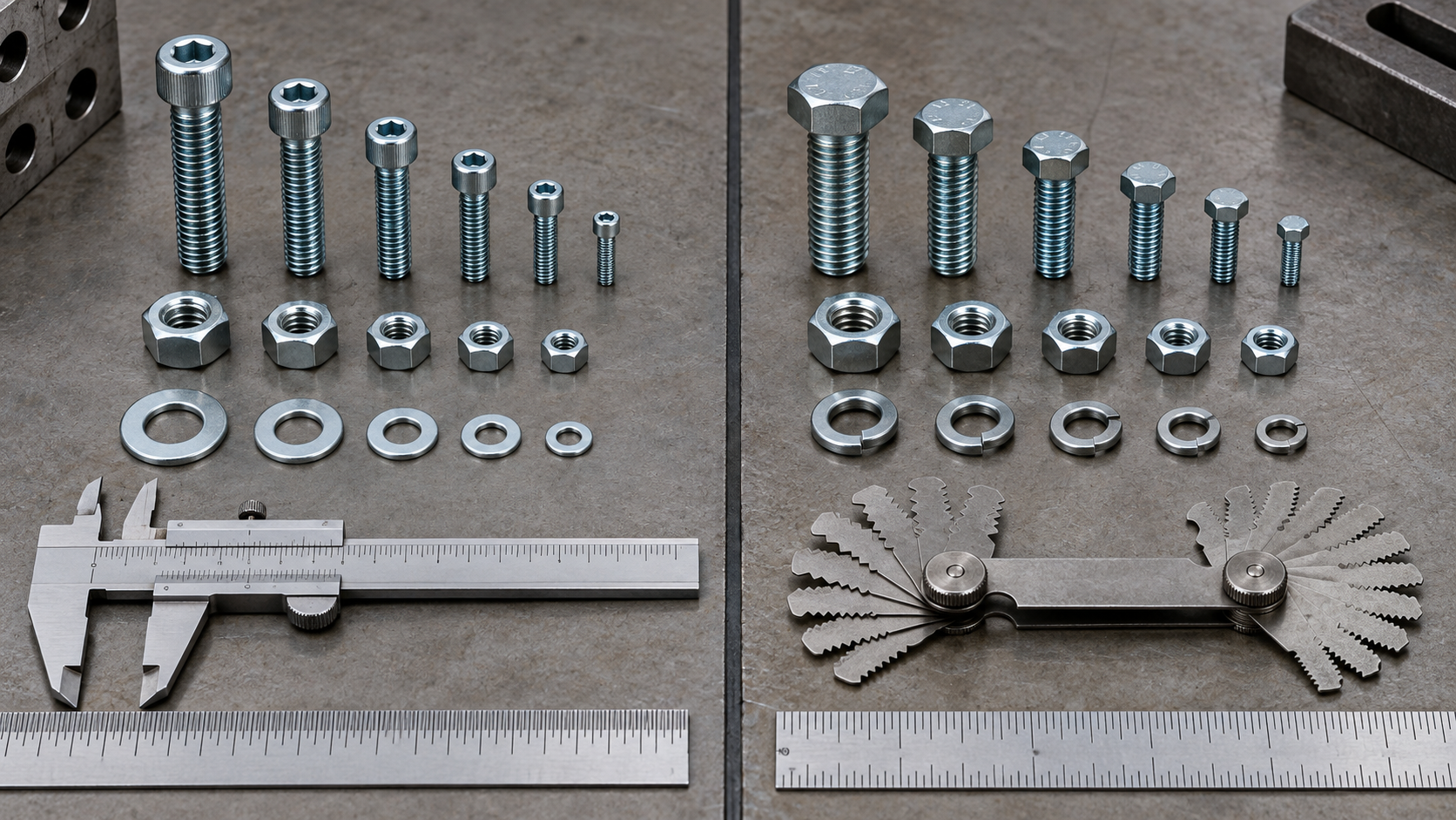
Imperial screw size chart: UNC and UNF
Unified inch threads use a nominal diameter and a thread count per inch. UNC means Unified National Coarse and UNF means Unified National Fine. ASME B1.1-2024 defines the unified inch thread form, series, class, allowance, tolerance, and designation. The following rows are common reference combinations; the full callout may also need a thread class and product standard.
| Nominal size | Approx. major diameter | UNC TPI | UNF TPI |
|---|---|---|---|
| #2 | 0.0860 in | 56 | 64 |
| #4 | 0.1120 in | 40 | 48 |
| #6 | 0.1380 in | 32 | 40 |
| #8 | 0.1640 in | 32 | 36 |
| #10 | 0.1900 in | 24 | 32 |
| 1/4 in | 0.2500 in | 20 | 28 |
| 5/16 in | 0.3125 in | 18 | 24 |
| 3/8 in | 0.3750 in | 16 | 24 |
| 7/16 in | 0.4375 in | 14 | 20 |
| 1/2 in | 0.5000 in | 13 | 20 |
The number after the dash is TPI, so 1/4-20 UNC has a 1/4 inch nominal diameter and 20 threads per inch. An inch fastener marked only “1/4” is incomplete for ordering because it does not identify the thread series or length. Do not treat a similar metric diameter as interchangeable with an inch thread; the pitch and thread form must mate.
How to read a screw size callout
A useful callout lets another person order or inspect the same part without guessing. Read the fields in this order:
- Thread system: metric, unified inch, pipe, or a special thread family.
- Nominal diameter: the basic outside diameter of the thread, such as M8 or 1/4 in.
- Pitch or TPI: the distance between metric thread crests or the number of inch threads in one inch.
- Length: measured from the correct head reference point to the tip.
- Head and drive: socket cap, hex flange, pan, countersunk, set screw, or another form, plus the drive recess.
- Material, grade, finish, and tolerance: the fields that make the fastener suitable for the load, environment, and mating part.
For example, M8 × 1.25 × 40 mm socket head cap screw, stainless steel, passivated gives a buyer much more control than “8 mm stainless screw.” If the part is a flange bolt, a DIN 6921 hex flange bolt page may be the better product route after the thread size has been confirmed.
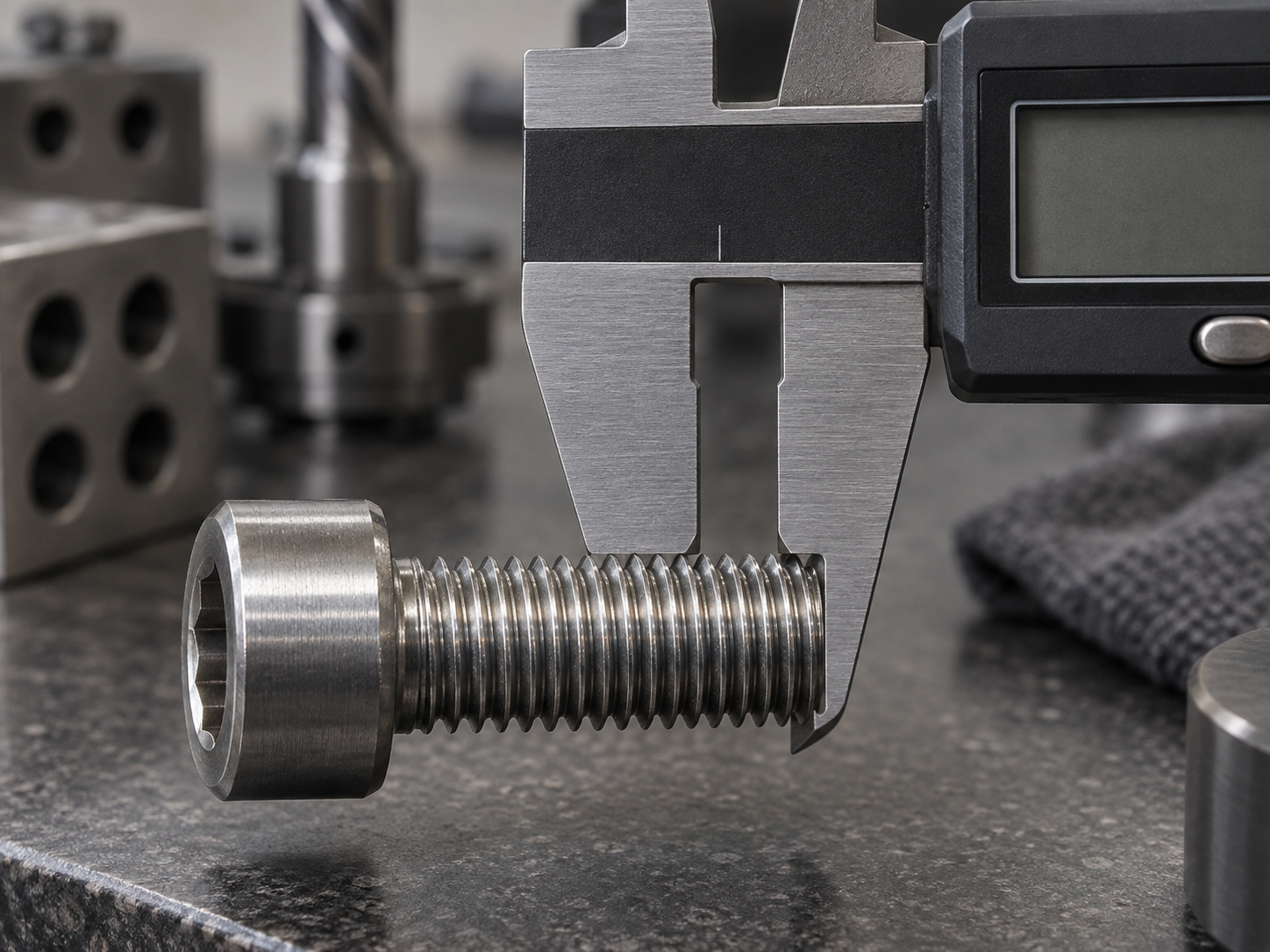
How to measure screw diameter, pitch, and length
1. Measure nominal diameter
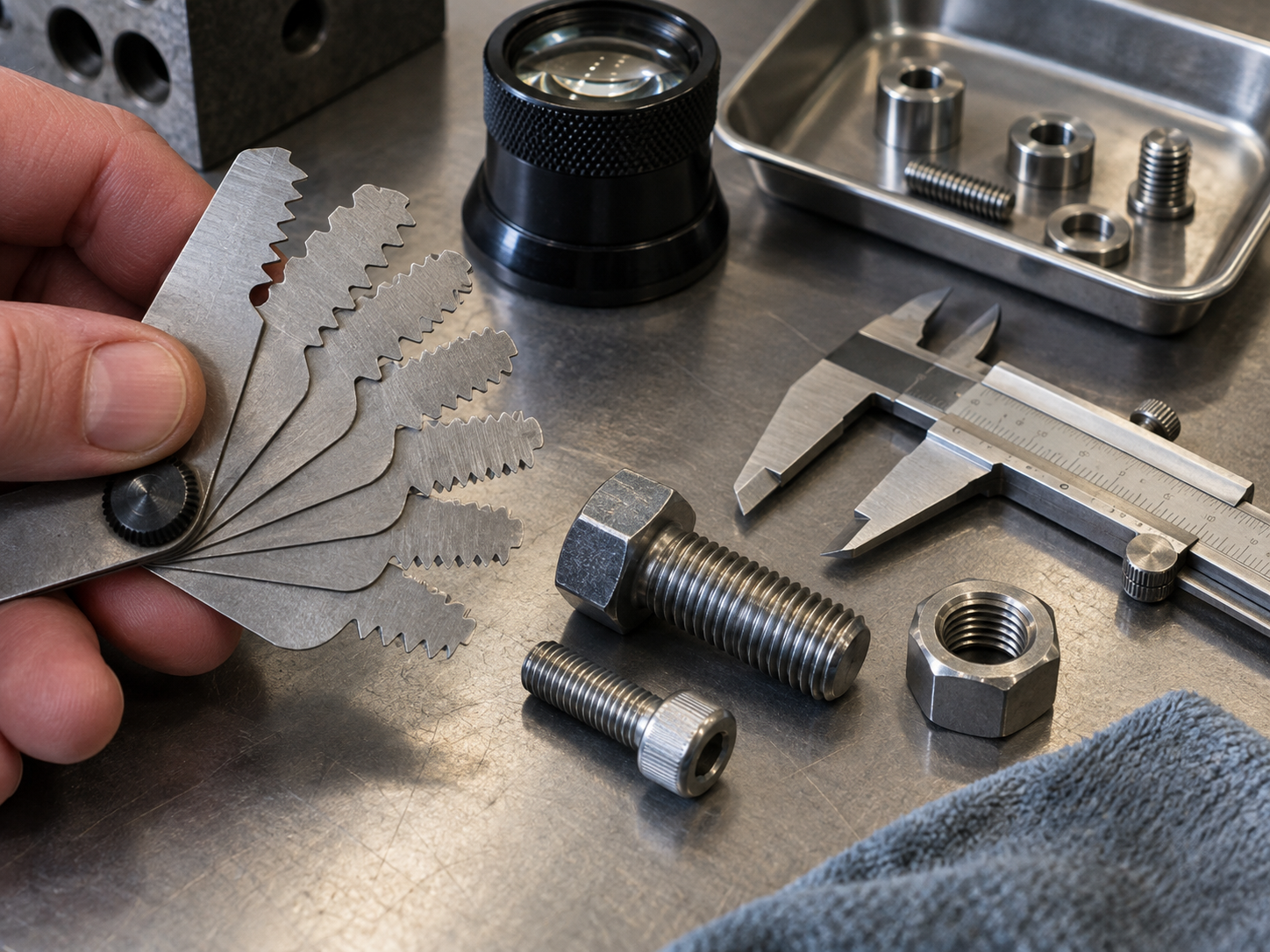
Use a clean caliper and measure across the threaded outside diameter. The reading will vary slightly from the nominal designation because of manufacturing tolerance, thread geometry, wear, dirt, coating, and the position of the jaws. A reading close to 8 mm suggests an M8 family, but it does not prove the pitch or tolerance class. Record the measurement and compare it with a thread gauge or known mating nut.
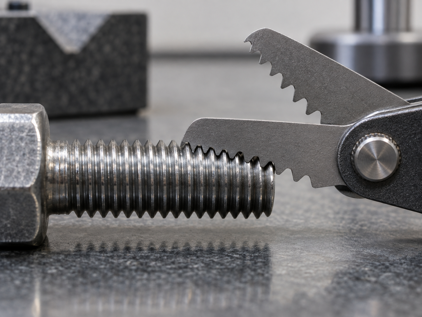
2. Confirm pitch or TPI
Metric pitch is the distance in millimetres from one thread crest to the next. Inch thread pitch is normally written as TPI, which counts crests across one inch. A thread pitch gauge is faster and more reliable than trying to judge the spacing by eye. Try a leaf until the teeth seat cleanly without rocking; use a second method when the fastener is damaged or coated.
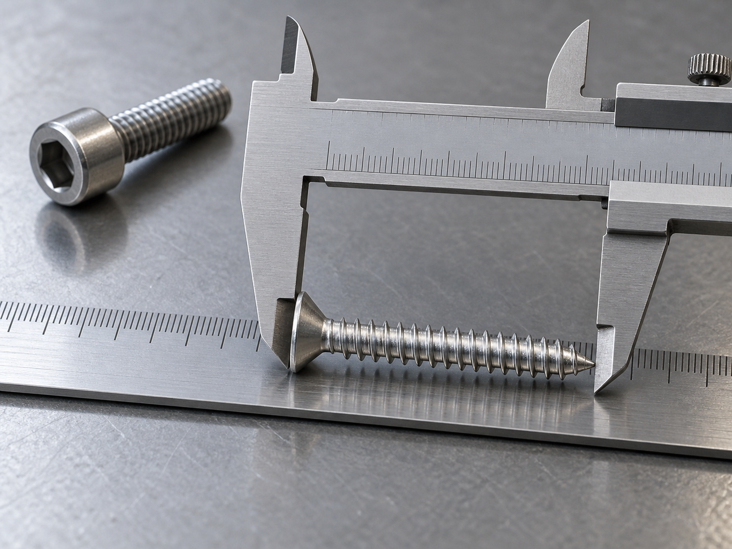
3. Measure length from the correct head reference
For most non-countersunk screws and bolts, measure from the underside of the head to the tip. For a countersunk screw, measure the overall length from the top of the head to the tip because the head sits inside the material. Set screws without a projecting head are usually measured end to end. If the part has a shoulder, record the shoulder length separately.
4. Check the mating part
Test the candidate screw in a known mating nut, tapped hole, or thread gauge by hand. It should start smoothly and turn without binding. Do not force a fastener to prove that it fits. A damaged thread, wrong pitch, coating buildup, or mixed metric/inch pairing can damage the mating component and create a misleading measurement.
Head style, drive, and clearance
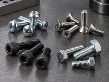
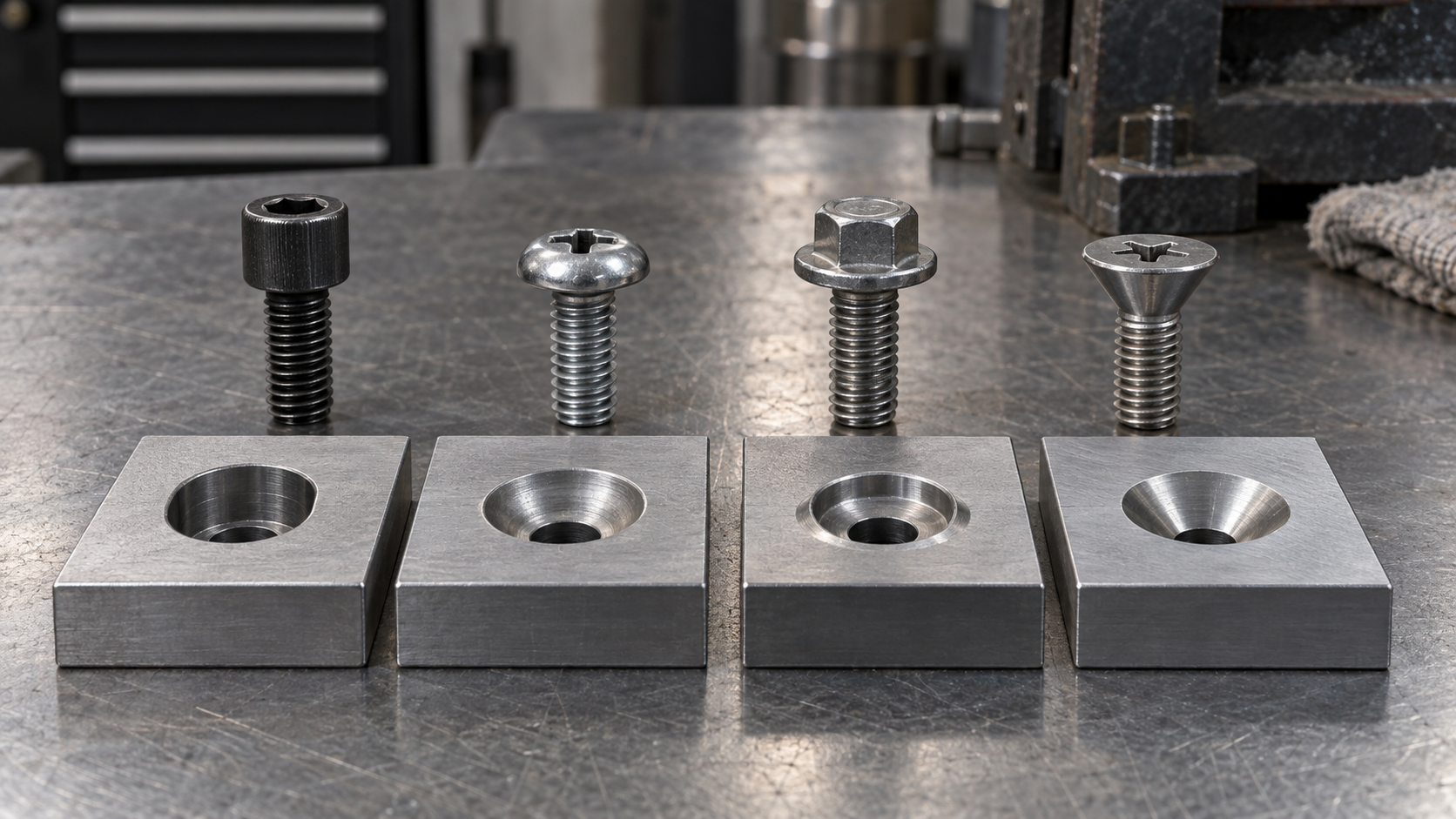
Two screws can share the same thread size while requiring different heads. Select the head from the installation surface, available tool access, clamping area, and required finished height. The drive recess must also match the assembly tool and the torque requirement.
| Head style | Useful when | Check before ordering |
|---|---|---|
| Socket cap | A compact cylindrical head and internal hex drive suit the assembly. | Socket depth, wrench access, head diameter, and clamp height. |
| Hex or flange | A wrench is available and the bearing surface needs more area. | Across-flats size, flange diameter, washer need, and clearance around the wrench. |
| Pan or button | A low-profile rounded surface is acceptable above the panel. | Head diameter, height, drive recess, and visible surface. |
| Countersunk | The head must sit flush or below the surrounding surface. | Countersink angle, seat diameter, overall length, and material thickness. |
Nut, washer, and thread pairing
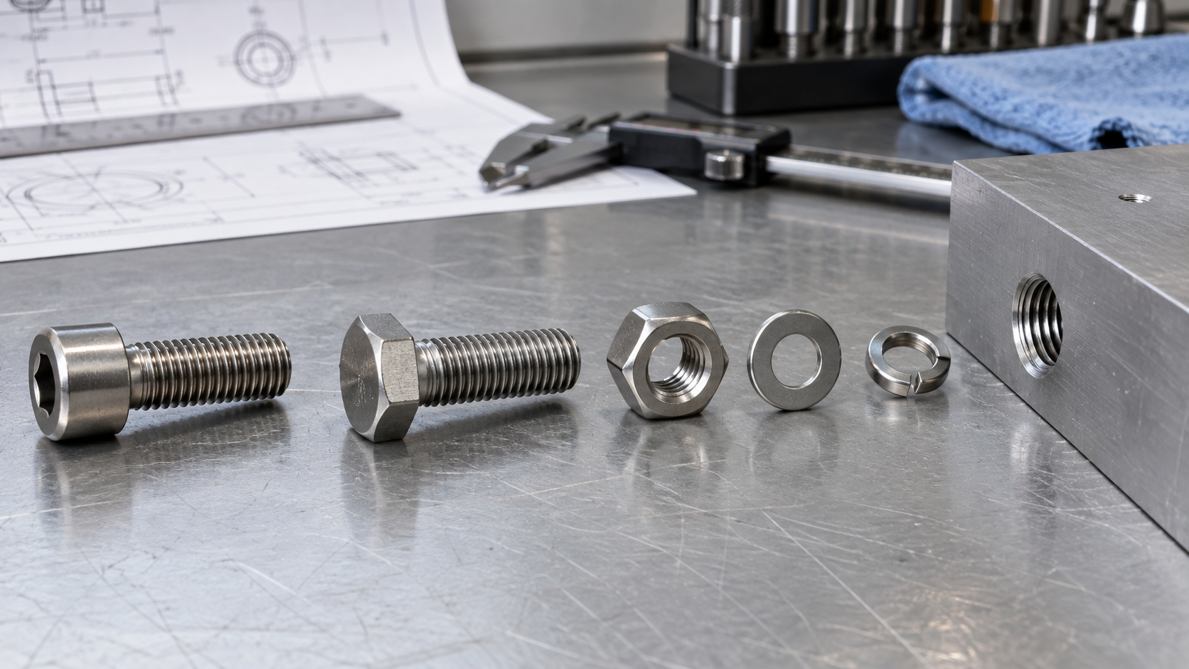
A size match is only useful when the mating components use the same thread system and pitch. Pair an M8 screw with an M8 nut using the specified pitch; pair a 1/4-20 UNC screw with a compatible 1/4-20 UNC nut. The washer bore, outside diameter, thickness, and washer standard should suit the hole and bearing surface.
- Confirm the nut thread and class before bulk ordering.
- Check whether the washer is plain, spring, serrated, sealing, or a special design.
- Allow for coating or plating on the mating thread where the fit is tight.
- Check the grip length: the screw should pass through the joint and engage enough thread without bottoming in a blind hole.
- Keep the full assembly drawing when the joint carries a defined load or sealing function.
Material, strength, and surface finish
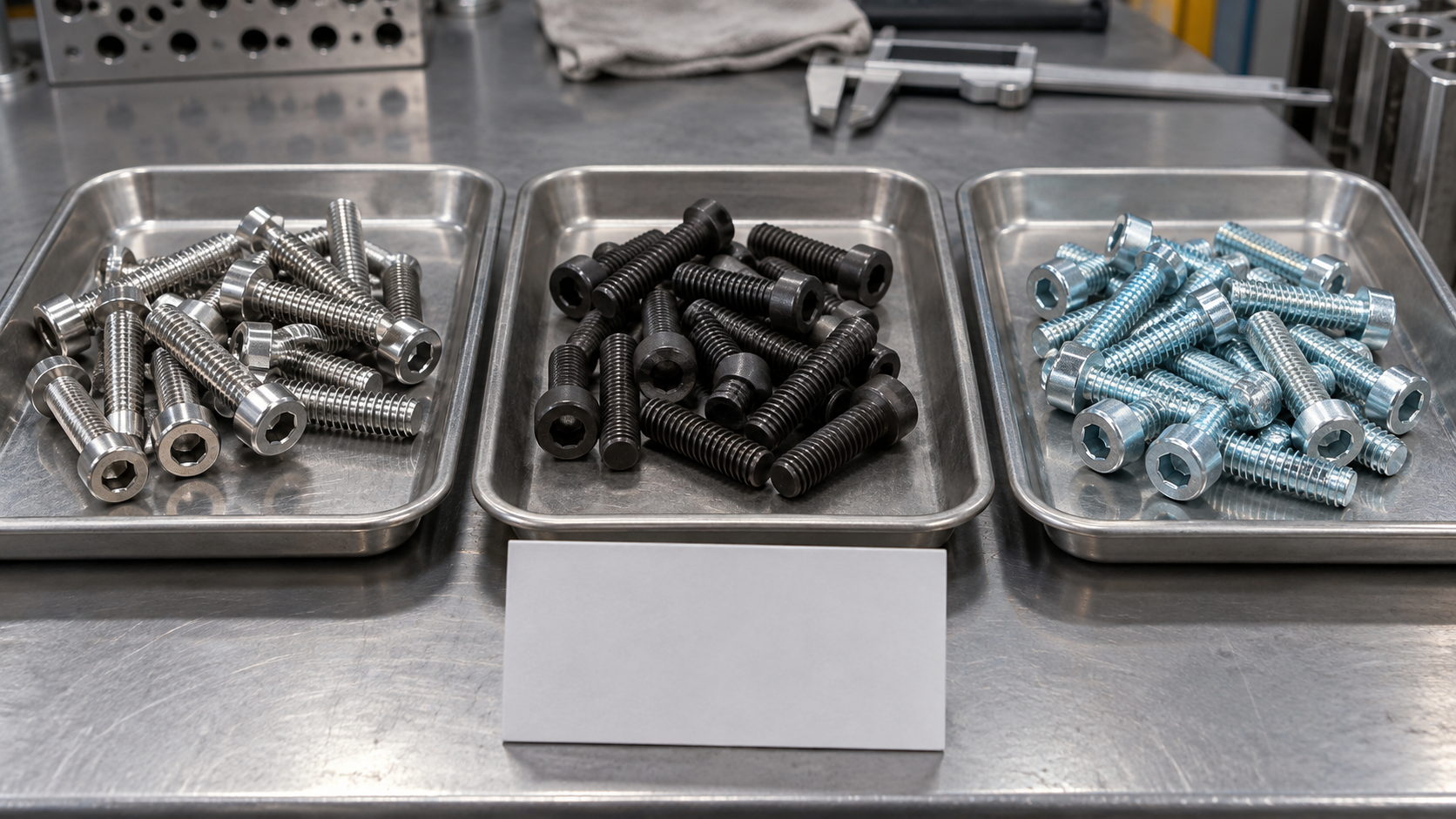
Diameter and length describe the geometry. Material, grade, and finish describe how the part behaves in the application. Common choices include stainless steel for corrosion resistance, carbon or alloy steel for defined strength requirements, and zinc-coated steel where the selected coating system suits the environment.
Choose a property class or grade from the joint design and governing standard. A stainless screw and a high-strength alloy steel screw with the same nominal size do not have the same mechanical behavior. Consider corrosion, galvanic contact with the mating material, temperature, assembly torque, hydrogen embrittlement risk for applicable coatings, and whether the finish changes the thread fit.
Bossard’s technical reference explains why thread dimensions and tolerances affect assembly and coating compatibility. Use that principle when reviewing a supplier drawing: the requested coating, tolerance, and thread class should be evaluated together. For grade terminology, our bolt grades guide provides a separate introduction.
Choose the size from the application
Use the chart to narrow the family, then use the joint design to select the final part. A tapped-hole assembly needs enough engaged thread and enough head access for the installation tool. A through-bolted joint needs the correct grip, nut, washer, and wrench clearance. A countersunk panel needs the right seat geometry and enough material around the hole.
| Application condition | Sizing questions | Helpful product route |
|---|---|---|
| Tapped blind hole | What is the usable depth, engagement, bottom clearance, and thread class? | Hexagon socket screws |
| Through-bolted joint | What is the joint grip, washer outside diameter, nut height, and wrench access? | Flange screws |
| Flush panel surface | What are the countersink angle, seat diameter, panel thickness, and overall length? | Countersunk socket bolts |
| Custom or unusual joint | Can you share a drawing, sample, material, finish, annual quantity, and inspection requirement? | Custom fastener solutions |

What to include in a screw RFQ
A supplier can respond faster when the request separates measured facts from assumptions. Send a drawing or sample whenever the joint is safety-critical, the thread is non-standard, or the head and tolerance are difficult to identify.
| RFQ field | Example of a useful entry |
|---|---|
| Thread designation | M8 × 1.25 or 1/4-20 UNC, including class where required. |
| Length and measurement rule | 40 mm under-head length, or 40 mm overall for a countersunk screw. |
| Head and drive | Socket cap, hex flange, pan, countersunk, set screw, and drive type. |
| Material and grade | Material, property class or grade, and any heat-treatment requirement. |
| Finish and environment | Finish, corrosion environment, temperature, and contact with dissimilar metals. |
| Quantity and supply format | Sample quantity, trial order, bulk quantity, packaging, and label requirements. |
| Quality documents | Inspection report, material certificate, coating requirement, or customer-specific document. |
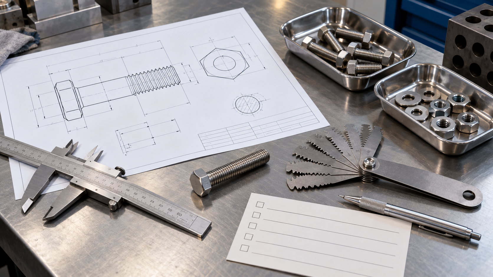
How a supplier should verify the final size
Before a production batch, the final part should be checked against the agreed drawing or product standard. Dimensional review can include diameter, pitch, length, head dimensions, drive depth, bearing surface, thread gauge fit, material, finish, and packaging identification. The exact inspection plan depends on the part and the customer requirement.
Ask the supplier to resolve any mismatch between the physical sample and the drawing before production. A good technical review records which dimensions came from a sample, which came from a standard, and which were confirmed by the buyer. This creates a clean handoff between engineering, purchasing, production, and incoming inspection.

Frequently asked questions about screw sizes
How do I read a screw size?
Read the thread system, nominal diameter, pitch or TPI, and length first. Then add head style, drive, material, grade, finish, and tolerance. A callout such as M8 × 1.25 × 40 mm identifies diameter, pitch, and length, but it does not describe the complete finished part by itself.
What does M8 × 1.25 mean?
It means an ISO metric thread with an 8 mm nominal diameter and a 1.25 mm pitch. A length must be added, such as M8 × 1.25 × 40 mm, and the head, material, finish, and applicable product standard should be specified for purchasing.
Is 1/4-20 the same as M6?
No. Their nominal diameters are close, but the thread forms and pitch systems differ. A 1/4-20 UNC fastener should mate with the specified inch thread, and an M6 fastener should mate with the specified metric pitch. Similar diameter does not make the parts interchangeable.
How is screw length measured?
Measure a projecting-head screw from the underside of the head to the tip. Measure a countersunk screw overall from the top of the head to the tip. Record the rule with the order because using the wrong reference point can change the usable grip length.
What is the difference between coarse and fine thread?
For the same nominal diameter, a coarse thread has fewer threads per inch or a larger metric pitch; a fine thread has more threads per inch or a smaller metric pitch. The correct choice depends on the joint, material, engagement, adjustment, and governing standard. Never substitute a pitch by appearance alone.
Can a thread pitch gauge identify the whole screw?
No. It helps identify the pitch or TPI. You still need the diameter, length, head, drive, material, finish, and thread class or product standard. A gauge result is one part of the identification workflow.
Do the head and thread size determine the screw strength?
No. Strength depends on material, property class or grade, heat treatment, thread geometry, and the joint design. Confirm the required grade and test or inspection documents from the drawing or customer specification.
What should I send a manufacturer for a custom screw quote?
Send a drawing or clear sample when possible, plus thread designation, length rule, head and drive, material, grade, finish, quantity, application, packaging, and quality documents. If any field is unknown, say so and ask for a technical review before production.
Standards and technical references
- ISO 262:2023 — selected metric diameter and pitch combinations for bolts, screws, studs, and nuts.
- ISO 724:2023 — basic dimensions for ISO general purpose metric screw threads.
- ASME B1.1-2024 — unified inch thread form, series, designation, allowance, and tolerance.
- Bossard metric ISO thread technical reference — dimensions, tolerances, coating, and assembly-fit considerations.
Send your screw drawing for review
If the chart narrows the family but the head, grade, finish, tolerance, or packaging is still uncertain, send the drawing or a physical sample to the DingLong Hardware team. Ask for a technical review, sample route, and bulk quotation based on the confirmed specification.

Related fastener guides
Check the narrower M2 chart and head specifications.
What Is Thread Pitch?
Review metric pitch and screw thread identification.
Types of Screws and Fasteners
Explore head, drive, bolt, nut, and washer names.
DIN 6921 Hex Flange Bolt
Review one product-standard flange fastener route.
Metric Thread Guide
Continue with metric thread sizes and standards.
Custom Fastener Solutions
Move from a chart result to drawing-based sourcing.