 English
  German
  Spanish
  Portuguese
  French
  Japanese
  Arabic
  Korean
  Vietnamese
  Russian
 Taper Pins: Sizes, Standards, Applications, and Installation Guide
Direct answer: Taper pins are solid conical fasteners used with matching tapered holes. As a pin seats, its shallow taper creates wedging friction that locates and retains two or more parts. The joint can still be released with a controlled punch or puller, which makes taper pins useful when an assembly must return to the same position after service.
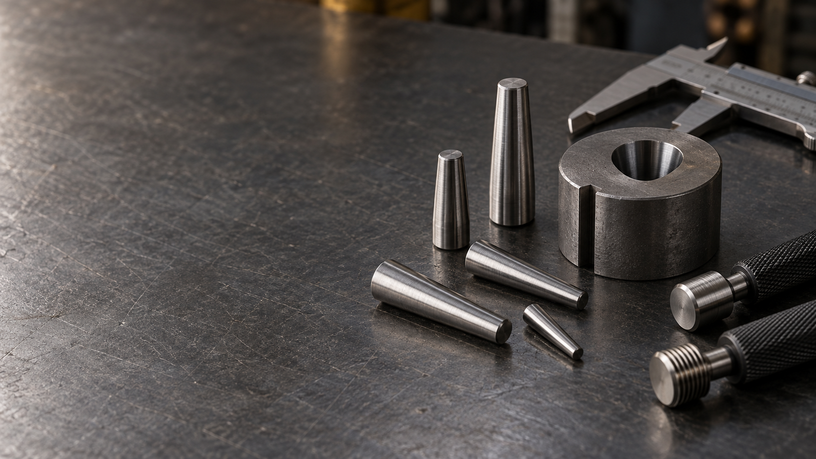
The name sounds simple, but taper pin orders often fail for a less obvious reason: the metric and inch systems do not use the same reference end for the nominal diameter. A buyer may measure the large end, copy the number into an inch-style request, and receive a part that does not match the existing hole. This guide covers identification, standards, reaming, installation, inspection, and the information a supplier needs for a custom quote.
What are taper pins and how do they hold?
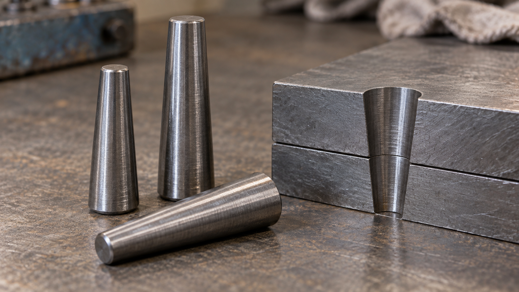
A taper pin is a solid round pin whose diameter changes gradually along its length. It is installed in a tapered bore made through the parts being joined. When the pin moves into the bore, the conical surfaces develop radial contact and friction. That contact keeps the parts located and resists movement in normal service.
This is different from a straight pin pressed into an undersized parallel hole. A straight pin depends on interference and hole tolerance. A taper pin depends on the geometry of the pin and bore working together. That difference affects the drawing, the reamer, the way the pin is seated, and the way it will be removed later.
Taper pins are often chosen for three jobs at once:
- locating two parts in a repeatable position;
- retaining a lever, hub, handwheel, fixture, or similar component;
- allowing disassembly without losing the original register.
The pin is not a universal replacement for a bolt, shaft key, or structural joint. If the assembly carries a large torque, shock load, fatigue load, or safety-critical load, the joint designer still needs to check the pin, hole, surrounding material, and load path as a complete system.
Taper pin sizes and the measurement rule that prevents ordering errors
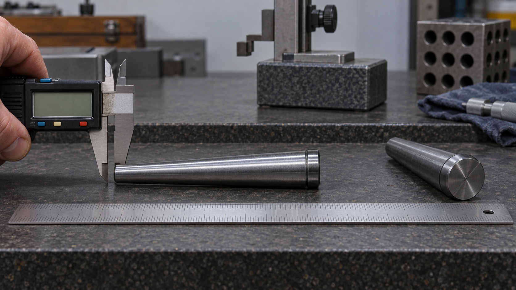
Start by deciding whether the existing part follows a metric or inch convention. Metric taper pins are commonly identified by the small-end diameter. Inch taper pins are commonly identified by the large-end diameter. The two conventions describe similar geometry, but they are not interchangeable.
| System | Common reference | Typical taper convention | Nominal diameter reference | What to record |
|---|---|---|---|---|
| Metric | ISO 2339 / DIN 1 | 1:50 | Small end | Small-end diameter, overall length, finish, tolerance, and hole condition |
| Inch | ASME B18.8.2 | 1:48, or 1/4 inch per 12 inches | Large end | Large-end diameter, overall length, series, finish, and hole condition |
For a quick geometry check, the diameter change is approximately the length divided by the taper denominator. A metric pin with a small-end diameter of d and length L has a large-end diameter close to d + L/50. For a common inch pin, the small end is close to the large-end diameter minus L/48. These are inspection calculations, not a substitute for the governing dimensional standard. Chamfers, end features, tolerance, and the exact standard can change what a caliper sees.
The official ISO 2339:1986 reference covers metric unhardened taper pins with nominal diameters from 0.6 mm through 50 mm. A practical DIN 1 and ISO 2339 sizing reference also shows why the end used for measurement matters. When replacing a part, measure the pin and inspect the bore. Do not identify the size from a single end measurement without recording which end you measured.
If the old pin is damaged, a length measurement can still help, but diameter and hole fit deserve more attention. A worn bore may accept a new pin too deeply. In that case, the replacement should follow a repair drawing or a controlled reaming plan rather than the old pin alone.
Taper pin standards and common forms
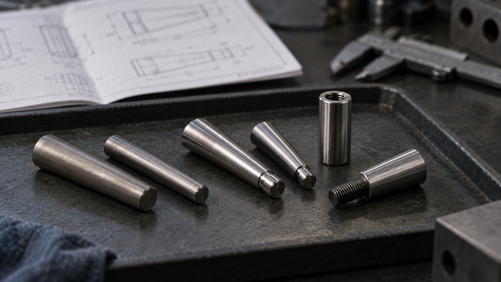
The standard belongs in the purchase description because the words “taper pin” do not define every dimensional detail. The standard determines the measurement convention, size series, end form, and related requirements.
- ISO 2339 / DIN 1: metric unhardened taper pins. ISO lists nominal diameters from 0.6 mm through 50 mm in its scope.
- ASME B18.8.2: the inch-series standard covering dimensional and general data for taper pins along with dowel, straight, grooved, and spring pins. The ASME description also notes supplementary information for drilling taper-pin holes.
- ISO 8736: metric unhardened taper pins with an internal thread. The thread gives a blind-hole assembly a place for a draw bolt or removal tool. See the ISO 8736 scope before selecting a threaded form.
- ISO 8737: metric unhardened taper pins with an external thread. The threaded end can work with a washer and nut or another retention arrangement. The ISO 8737 reference lists the dimensions and designation information covered by that standard.
Some catalogs also distinguish ground and turned surface forms. That distinction matters when the pin locates a precision fixture or moves in a controlled assembly. If the finish or tolerance affects the fit, write it on the drawing. A supplier should not have to infer it from the word “precision.” For thread terminology and measurement basics, the site guide on what thread pitch means can be used alongside the pin standard.
Taper pins versus dowel pins and straight pins
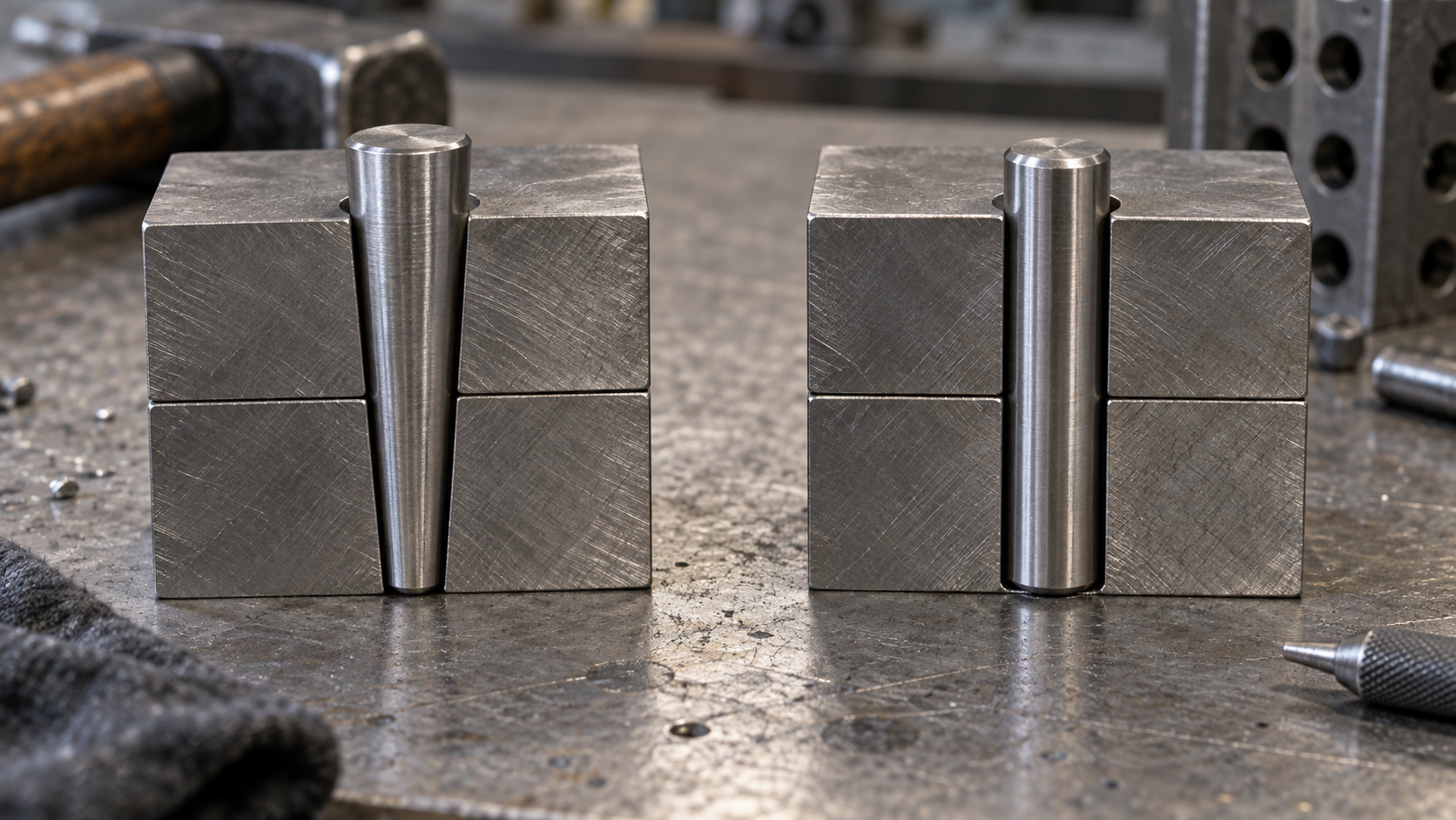
Both pin types can locate parts, but they solve different maintenance problems. A taper pin uses a shallow wedge. A dowel pin is cylindrical and normally relies on a controlled fit in a parallel hole. One part cannot be swapped for the other without checking the bore and the joint design.
| Question | Taper pin | Straight or dowel pin |
|---|---|---|
| Hole form | Matching tapered hole, usually drilled and taper reamed | Parallel hole with a specified fit and tolerance |
| Retention | Wedge action and friction along the taper | Interference, transition, or close fit depending on the design |
| Service access | Can be driven out when a punch path is available | May need a relief hole, puller, or press because the fit can be tight |
| Good fit for | Repeatable location with planned removal and reassembly | Permanent or semi-permanent location where a parallel fit is preferred |
Choose a taper pin when the design benefits from a defined seating position and future removal. Choose a straight or dowel pin when the drawing is built around a parallel bore, precise interference, or a hardened locating system. If the assembly is exposed to vibration or cyclic load, review the full joint instead of assuming either pin will hold simply because it fits the hole.
Applications that benefit from a tapered joint
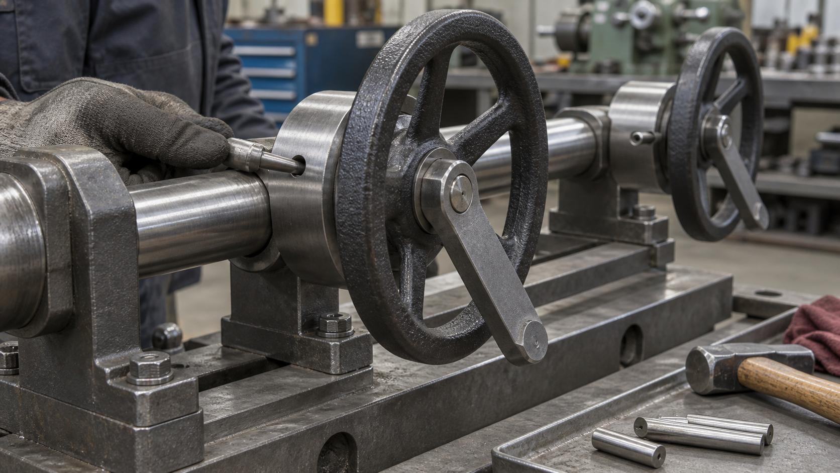
Taper pins are a good match for components that need to come off and return to the same register. Common examples include:
- handwheels, levers, cranks, and control handles on shafts;
- hubs, pulleys, gears, and other rotating parts that need indexed positioning;
- jigs, fixtures, dies, and machine plates that are removed during maintenance;
- alignment of mating machine parts where a straight drilled hole would not provide the desired seating behavior;
- service tools or assemblies where an internal thread makes extraction possible from a blind hole.
Design the removal route at the same time as the installation route. A plain pin in a through hole can be simple to service. A blind hole may need an internal-threaded form, a relief hole, or enough clearance for a puller. If the pin will transmit torque through a shaft or hub, review keying, shoulder contact, wall thickness, and bearing stress as well as the pin diameter.
How to prepare a tapered hole
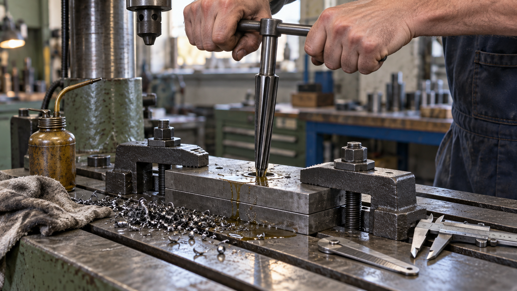
A tapered hole is usually made in two stages: drill a pilot hole through the aligned parts, then finish the bore with the correct taper reamer. The archived technical manual on drilling and reaming tapered pins describes this sequence and ties the pilot drill to the minimum diameter of the selected pin.
- Set the parts in their final relationship. Clamp the pieces so the hole will not shift when the drill or reamer passes through the joint.
- Mark the pin location and check access. Confirm the direction of installation and leave a clear path for the punch or removal tool.
- Drill the pilot hole. Select the drill from the small-end requirement and the drawing. The pilot should remove most of the material while leaving the reamer enough stock to create the taper.
- Use the matching taper reamer. Match the reamer to the pin system, nominal size, and taper ratio. A straight reamer cannot create the intended seating surface.
- Clean and deburr the bore. Remove chips, burrs, and cutting fluid that could keep the pin from contacting the taper evenly.
- Check the actual pin. Test the pin in the assembled parts and record the seating depth or exposed-end condition required by the drawing. Ream a small amount at a time if the pin stops too high.
A hole that is too shallow at the mouth can leave contact concentrated near one end. A hole that is over-reamed can let the pin drop too far, reduce the available removal surface, or change the relationship between the joined parts. For production work, define the hole process and inspection method instead of relying on a visual flush check alone.
Installation and removal practices
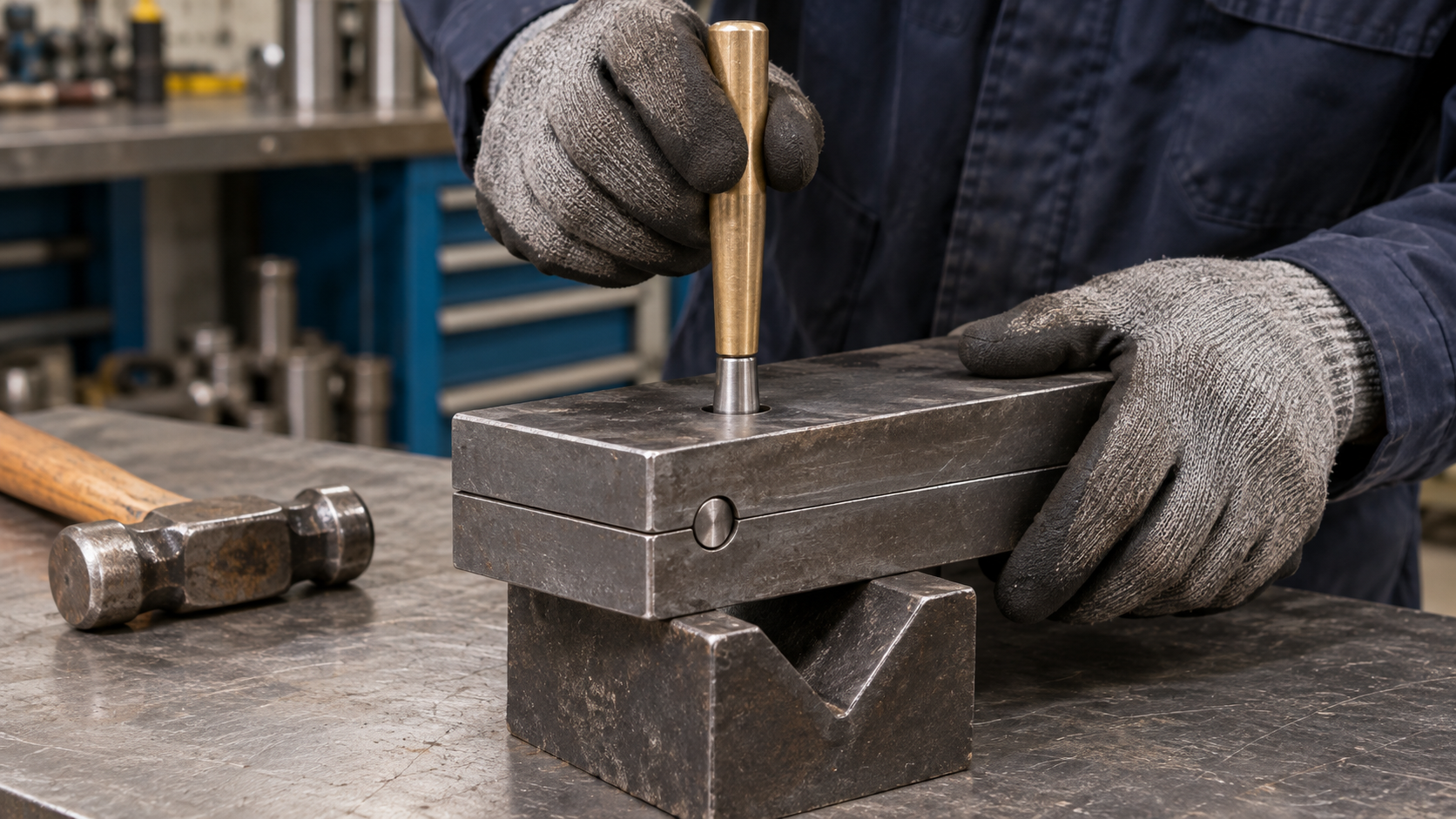
Before installation, clean the pin and bore, confirm the parts are aligned, and support the assembly close to the hole. Seat the pin with a flat-faced punch or the tool specified for the assembly. A few controlled blows are easier to evaluate than repeated heavy blows. Stop when the planned seating depth or exposed-end condition is reached.
Do not use the pin to pull badly misaligned parts together. If the pin will not enter close to its expected position, inspect the bore, alignment, burrs, and pin size before increasing force. A damaged pin end makes later removal harder and can hide a problem with the hole.
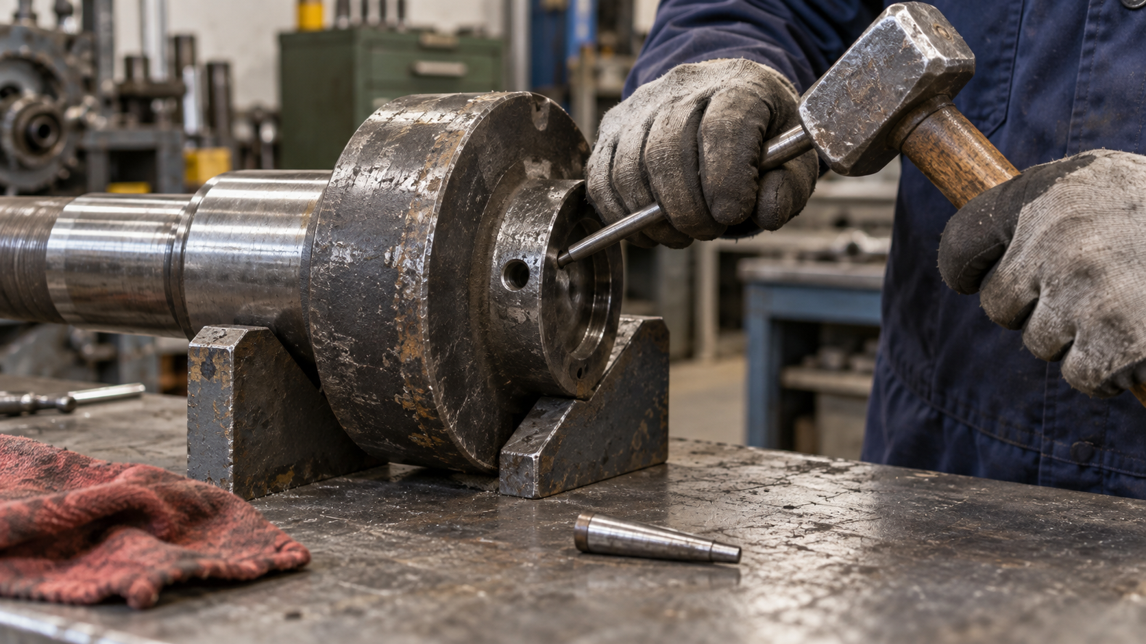
For a plain taper pin, support the work and drive from the small end with a punch slightly smaller than the pin end. Use a removal tool that will not spread the pin or damage the bore. The maintenance procedure should identify the small end before force is applied. If the pin is stuck, check for corrosion, burrs, deformation, or a load still trapped in the joint. An internal-threaded pin can be a better choice for a blind hole or an assembly that cannot accept a direct punch.
Replace a pin that has mushroomed, scored, or lost its surface condition. Reusing a damaged pin can change the seating depth and make the next inspection misleading.
Material, finish, and quality checks
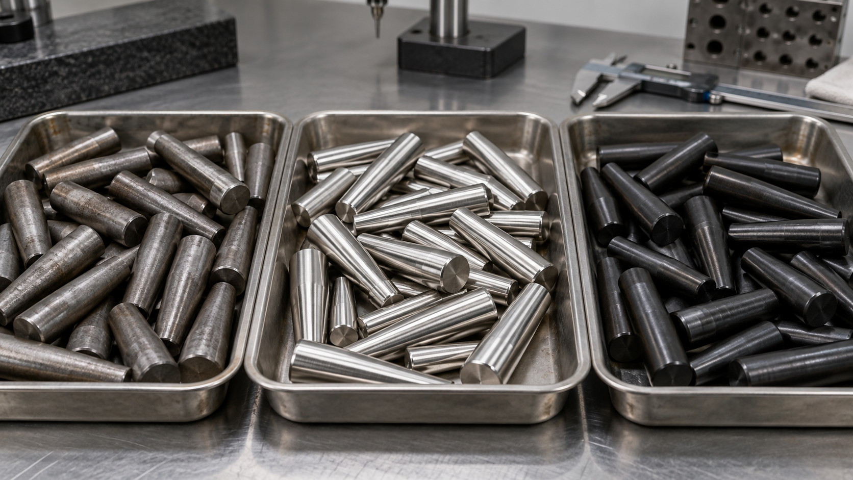
Common material choices include carbon steel for general mechanical use, stainless steel for corrosion-sensitive environments, and alloy or hardened steel where wear and repeated service matter. The right choice depends on the mating materials, load cycle, temperature, corrosion exposure, and required surface condition. Material alone does not establish a safe load rating.
Ask the supplier to identify the material grade, heat treatment or hardness requirement when applicable, surface finish, and corrosion protection. If a stainless pin will sit in a dissimilar metal, review galvanic exposure and galling risk. If a finished pin locates a precision fixture, include surface finish and dimensional tolerance in the drawing.
A practical receiving inspection can include:
- large-end or small-end diameter measured according to the selected standard;
- overall length, chamfer, thread, and end condition;
- taper checked with a suitable gauge, comparator, or verified mating bore;
- surface condition checked for burrs, tool marks, corrosion, or coating damage;
- sample fit checked in a controlled reference hole or the production assembly.

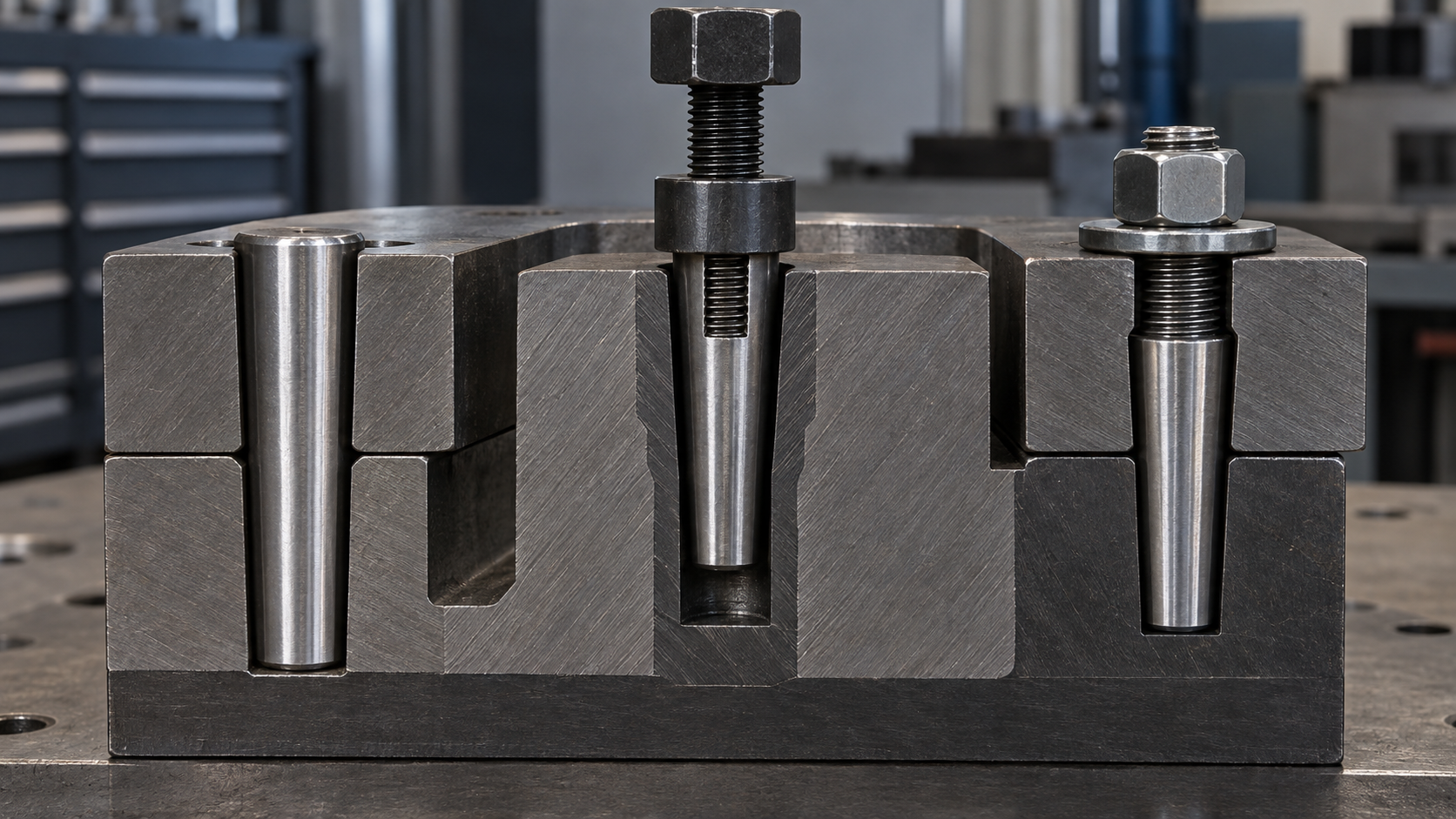
Use an internal-threaded form when the extraction tool must pull from inside a blind hole. Use an external-threaded form when a washer and nut or a draw arrangement fits the assembly. The threaded end changes the part description, so the thread size, thread length, material, and standard need to appear on the drawing. Do not add a thread to a plain-pin request by assumption.
What to include in a taper pin RFQ
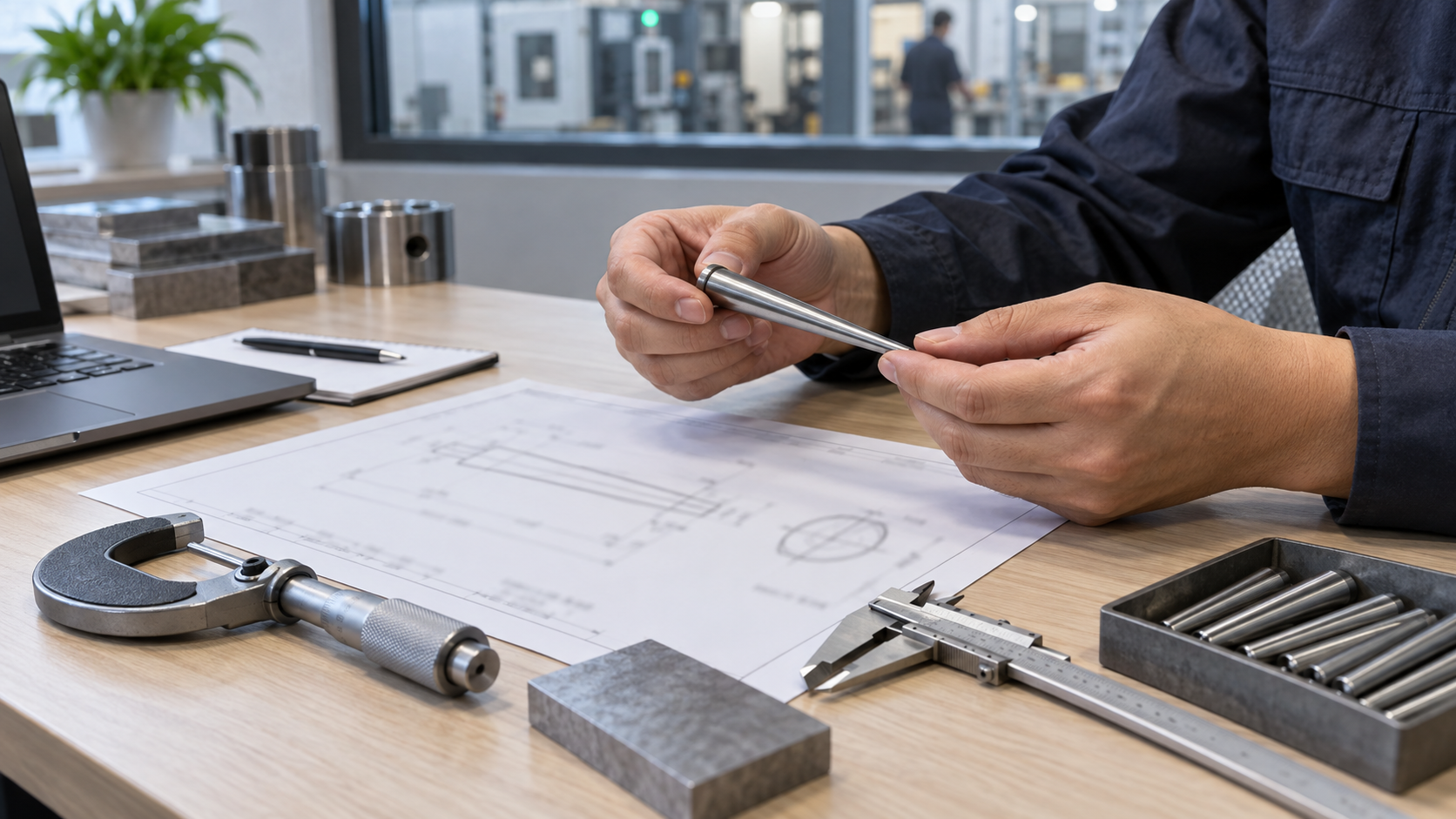
A supplier can quote faster when the RFQ answers the questions that cause the most rework. Include as many of these fields as the project allows:
- pin type: plain, internal threaded, external threaded, or another defined form;
- metric or inch system and the governing standard;
- nominal diameter with the measured end identified;
- overall length, seating depth, protrusion, and any end chamfer;
- mating hole drawing, hole angle or taper, pilot-hole process, and joined materials;
- material grade, hardness or heat treatment, surface finish, and corrosion protection;
- inspection points, sample approval, certificate needs, and packaging requirements;
- quantity, order frequency, target delivery location, and required delivery window.
If the part is replacing an old pin, send a clear measurement record and photographs of both ends, the bore, and the installed position. A physical sample is useful, but it should travel with the drawing or a written description of which dimensions are controlling.
DingLong’s custom fastener solutions page describes support for non-standard fastener requirements. For a taper pin tied to a wider screw or bolt assembly, send the drawing, sample, material, finish, quantity, and hole information for review. Final material, process, tolerance, MOQ, and lead time depend on the part details.
Taper pin FAQ
What is the standard taper for metric taper pins?
The common metric taper convention for DIN 1 and ISO 2339 taper pins is 1:50. That means the diameter changes by about 1 mm over 50 mm of length. Use the governing dimensional standard for production values because chamfers and tolerances affect the measured ends.
What is the standard taper for inch taper pins?
Common inch taper pins use a 1:48 diameter taper, also described as 1/4 inch per 12 inches. Inch sizing is commonly referenced at the large end. Confirm the exact ASME series and supplier chart before ordering a replacement.
How are taper pins sized?
Metric pins are commonly sized by the small-end diameter and length. Inch pins are commonly sized by the large-end diameter and length. Always write the standard and the reference end in the RFQ so a measured number cannot be interpreted the wrong way.
Do taper pins need a special reamer?
Yes. A matching taper reamer prepares the tapered seating surface after the pilot hole is drilled. Select the reamer for the same size system, nominal pin size, and taper. A straight reamer leaves the wrong bore geometry.
Can a taper pin be used in a straight hole?
A standard taper pin is intended for a matching tapered hole. It may touch a straight bore at only a small area or wedge unpredictably, so a straight hole should not be treated as an acceptable substitute without a design review.
Which way should a taper pin be removed?
For a plain pin, identify the small end and drive it out with a suitable punch while supporting the assembly. Leave a clear removal path in the design. An internal-threaded taper pin can provide a controlled extraction method when direct driving is not practical.
Are taper pins and dowel pins interchangeable?
No. A taper pin needs a tapered bore and uses wedge friction. A dowel pin is straight and uses a specified fit in a parallel bore. Changing pin types can alter location, seating depth, removal force, and the load carried by the surrounding material.
Can a manufacturer make custom taper pins?
Availability depends on the size, standard, material, finish, threaded form, quantity, and drawing. Send the pin and hole information together. A supplier can then confirm whether the requirement fits a standard part, a modified part, or a custom manufacturing review.
Specify the joint before you specify the pin
A taper pin works because its pin, hole, joined parts, and removal method were considered together. Start with the standard and the correct reference end, then confirm the taper, length, hole preparation, material, finish, and inspection method. That short discipline prevents most replacement and sourcing errors.
For a drawing-based request connected to custom screws, bolts, or other special fasteners, use the custom fastener solutions page and include the fields listed above.