 English
  German
  Spanish
  Portuguese
  French
  Japanese
  Arabic
  Korean
  Vietnamese
  Russian
 Cotter Pin Guide: Types, Sizes, Standards, and Installation
Direct answer: A cotter pin, also called a split pin, is a two-leg metal retaining fastener inserted through a cross-drilled hole in a bolt, clevis pin, shaft, or castellated nut. After insertion, the legs are bent to resist withdrawal. The cotter pin normally provides secondary retention; the bolt, nut, clevis pin, or shaft carries the primary joint load.
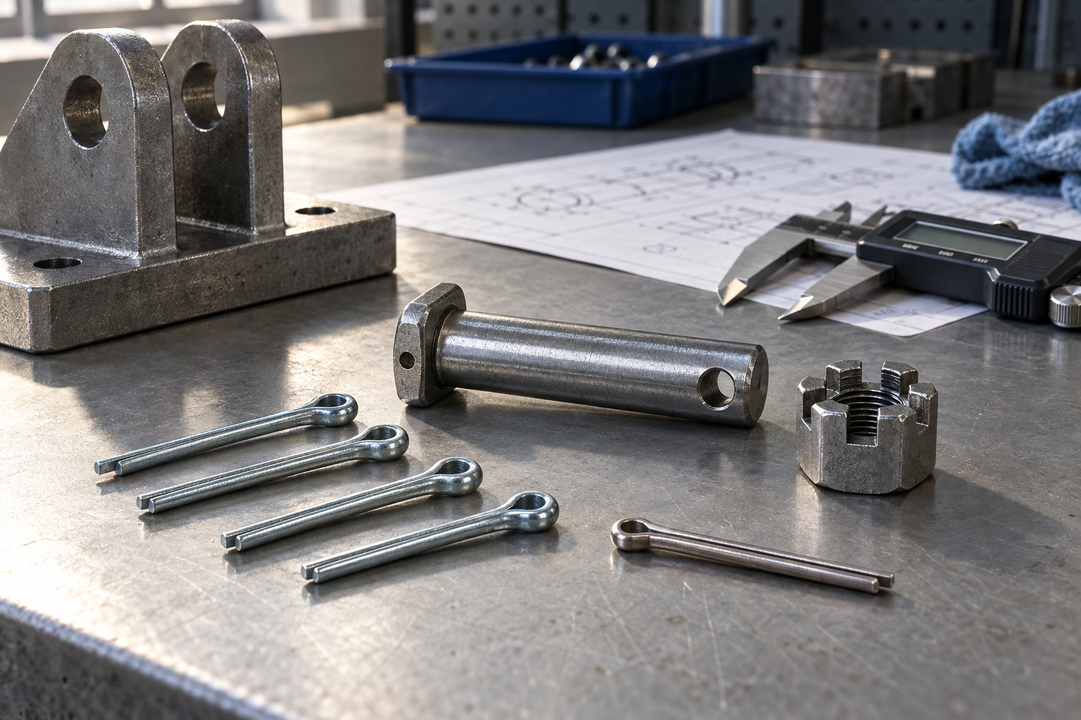
Buyers often search for a cotter pin when they actually need to solve one of four problems: stop a nut from backing off, retain a clevis pin, hold an axle or shaft component in place, or replace a deformed split pin during maintenance. The correct part depends on the hole diameter, available leg length, material, finish, standard, and the way the assembly will be serviced. This guide explains those decisions and lists the information a supplier needs to review a standard or custom requirement.
What is a cotter pin and how does it work?
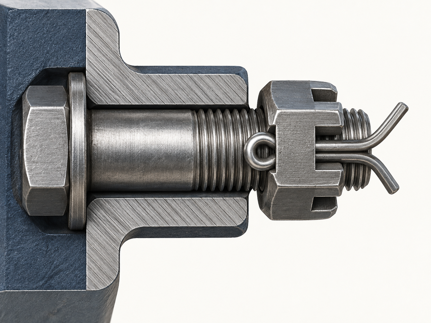
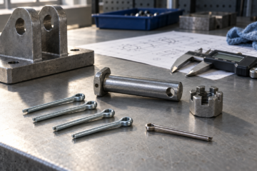
In fastener catalogs, a cotter pin is usually a small unthreaded pin made from wire with a looped head and two legs. The legs may have a half-round or similar cross-section, and their end form can vary by supplier or standard. The pin passes through an existing hole. Once the legs are bent away from the centerline, the head and legs create a visible mechanical stop.
A typical retaining sequence is:
- A bolt, clevis pin, shaft, or nut is made with a transverse hole or slot arrangement.
- The hole is aligned with the opening in the mating part or castellated nut.
- The cotter pin is pushed through until the head is seated against the surface.
- The two legs are bent in a controlled way so they cannot pass back through the hole.
The cotter pin does not set the nut torque, create clamp load, or replace a designed shear pin. With a castellated nut, the nut is tightened by the governing assembly procedure and the pin is then used as secondary retention through a slot and the bolt hole. With a clevis joint, the clevis pin carries the joint load and the cotter pin prevents axial escape.
For vibration, shock, cyclic loading, or safety-related assemblies, review the entire load path. Check the bolt or clevis pin, cross-hole location, nut, surrounding material, clearance, and the specified retaining method together. A pin that fits the hole can still be the wrong choice if the legs interfere with movement or the joint has no service access.
Cotter pin anatomy and the dimensions to record
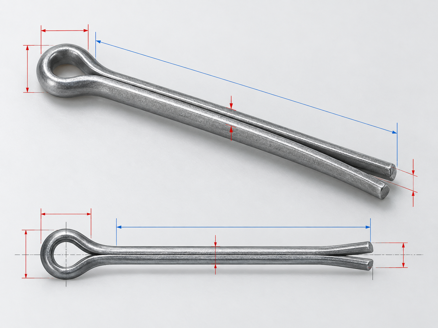
Before measuring a replacement, identify the features that matter to the assembly:
- Eye or head: the closed end that stops the pin at the entry surface.
- Shank or nominal diameter: the diameter used to select the cross-hole fit under the chosen standard.
- Two legs or tines: the split ends that are bent after insertion.
- Effective length: the usable length from the head contact point toward the leg ends. Catalogs can define this measurement differently, so record the supplier’s convention.
- Leg exposure: the amount that remains available to bend after the pin passes through the hole and nut or clevis.
- End form: square cut, bevel, mitre, or another controlled end condition when the application needs it.
Measure the old pin only after checking whether it was installed correctly. A pin bent too close to the head, cut too short, or forced through an oversized hole can give a misleading sample. Photograph both ends, the cross-hole, and the installed position. Note whether the pin is retained by a castellated nut, a clevis pin, a shaft, or another part.
Cotter pin types and common applications
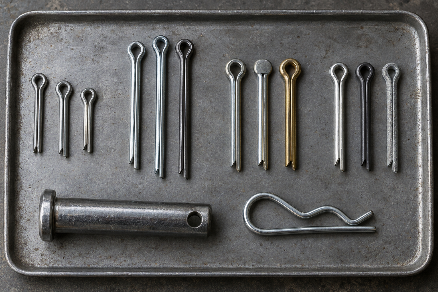
The basic form is a plain split pin. Catalogs may also list longer-leg variants, different head or end forms, corrosion-resistant materials, and specialty retaining products that are sometimes grouped with cotter pins. Do not treat every two-leg clip as dimensionally interchangeable. The standard, hole, bend method, and service requirement should control the selection.
| Application | How the cotter pin is used | Selection check |
|---|---|---|
| Castellated nut on a bolt or axle | The pin passes through the bolt hole and a slot in the nut to limit nut rotation or withdrawal. | Confirm the bolt hole, slot position, nut height, leg clearance, and assembly torque procedure. |
| Clevis pin joint | The pin passes through the hole at the end of the clevis pin and prevents axial escape. | Confirm the clevis pin hole, joint motion, exposed-leg clearance, and service access. |
| Axle, hub, or shaft retention | The pin provides a visible secondary stop for a washer, nut, or pin assembly. | Confirm that the primary load is carried by the designed shaft and bearing surfaces. |
| Linkage, hinge, or agricultural mechanism | The pin retains a pivot or linkage part while allowing planned maintenance. | Check vibration, dirt, corrosion, movement envelope, and replacement frequency. |
For an assembly that must be removed frequently, a reusable retaining clip may reduce service time. For a joint that needs a visible, low-cost secondary lock and already has a transverse hole, a split pin can be appropriate. The choice should follow the design drawing and maintenance procedure rather than the name used by a local catalog.
Cotter pin sizes and standards
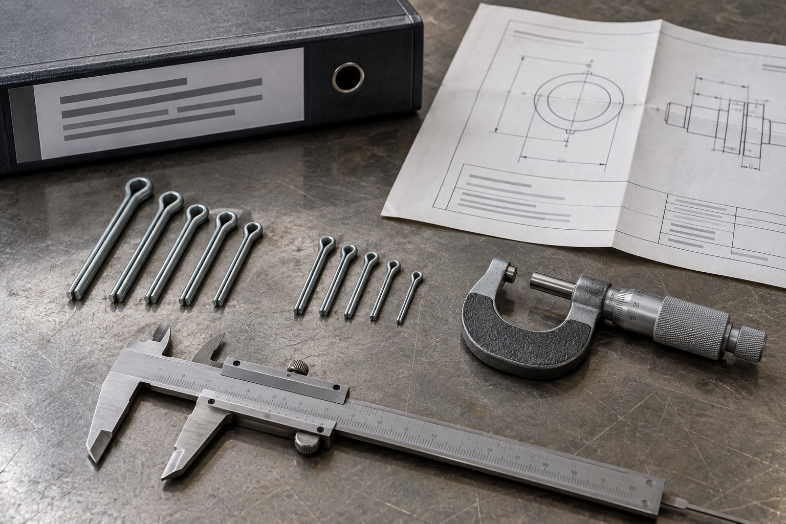
There is no single universal cotter pin size chart. The applicable standard defines the size series, dimensions, tolerances, and sometimes the recommended relationship between the pin and the mating bolt or clevis pin. A supplier should confirm the exact table before production.
- ASME B18.8.1: the ASME inch-series standard covers clevis pins and cotter, or split, pins. ASME lists cotter pin sizes from 1/32 through 3/4 inch in various materials and states that inclusion in the standard does not mean every described item is a stock product. See the ASME B18.8.1 reference for the scope.
- ISO 1234: the international split pin standard is the main ISO reference to check for a metric split pin requirement. The ISO 1234:1997 page identifies the standard as published and shows that it was confirmed in 2023.
- DIN 94: a common metric reference for cotter pins and split pins. A practical DIN 94 technical reference describes the bent-leg form, length measurement, tolerances, and use with clevis pins or transverse-hole bolts.
Use the standard as a crosswalk, not as a substitute for the drawing. ASME and ISO documents can use different designations, unit systems, and dimensional conventions. When a replacement crosses from inch to metric, the pin may pass through the hole but still provide the wrong clearance or leg exposure. If the existing part is unidentified, send the sample and hole measurements to the supplier for confirmation.
How to choose a cotter pin size
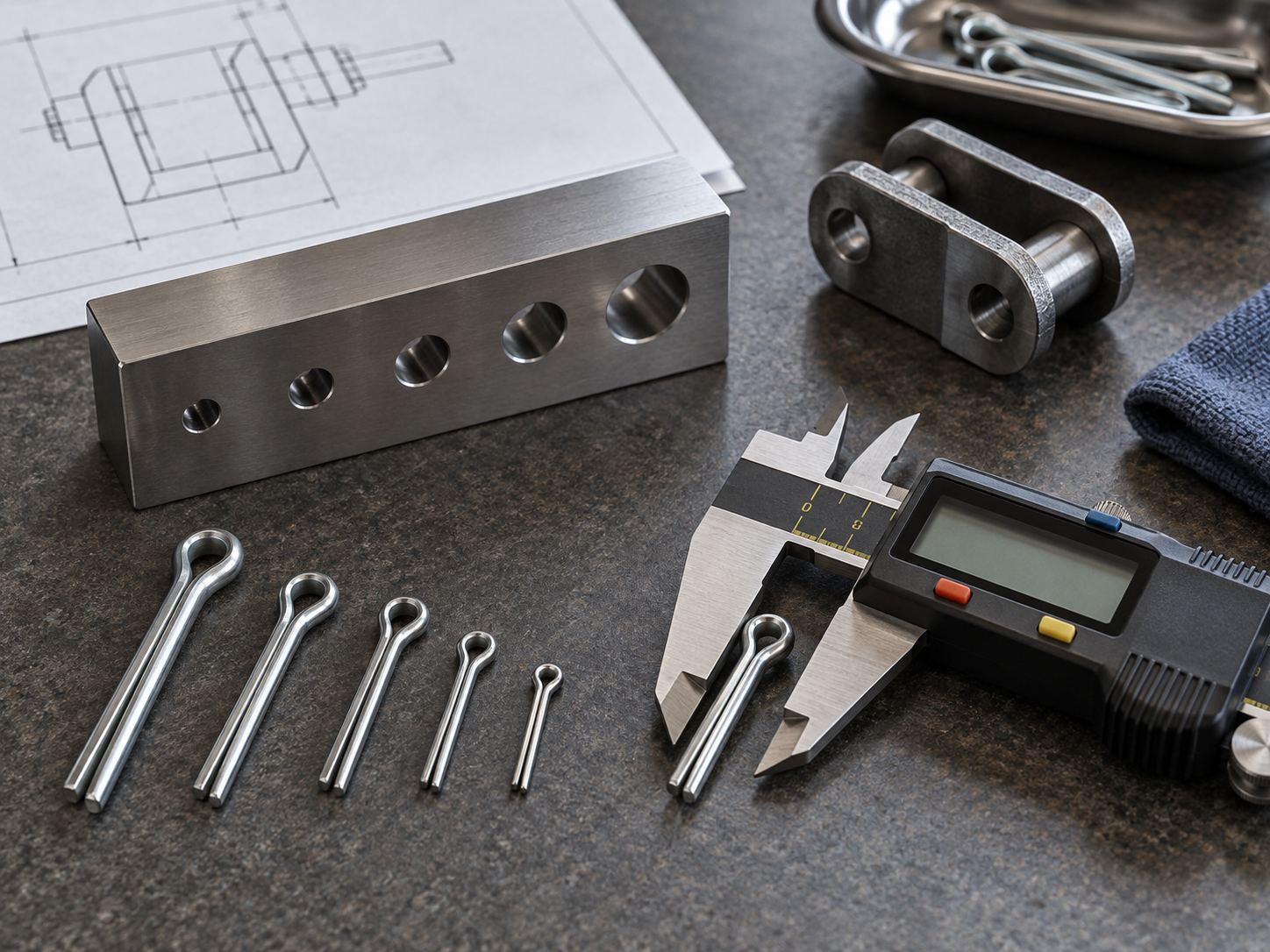
Start with the mating part, not the pin assortment. The cross-hole diameter, the part thickness, and the space around the legs determine whether the pin can be installed and locked without interference.
- Identify the retaining job. Write down whether the pin retains a castellated nut, clevis pin, bolt, shaft component, or linkage.
- Measure the cross-hole. Check the actual diameter and condition at both sides. A burr or worn hole can distort a caliper reading.
- Select the standard and unit system. Confirm inch or metric and identify the governing standard before choosing a nominal diameter.
- Check effective length. The pin must pass through the full joint and leave enough leg length to bend inside the clearance envelope.
- Check the head and leg clearance. The head must seat against the entry surface, and the bent legs must not catch a moving part, seal, hose, or operator.
- Confirm material and finish. Match corrosion resistance, wear, temperature, and contact with mating metals to the service environment.
For a castellated nut, install the nut to the specified torque or preload first. The slot should align with the cross-hole under the approved assembly method. Do not back off a torqued nut simply to make a slot line up unless the engineering procedure permits it. If alignment cannot be achieved within the allowed adjustment, review the nut, washer, bolt, or hole design.
For a clevis pin, confirm that the pin head or retaining shoulder is fully seated and that the cotter pin does not restrict the joint’s intended motion. If the hole is enlarged, oval, cracked, or heavily corroded, replacing only the cotter pin may leave the underlying retention problem unresolved.
How to install and remove a cotter pin
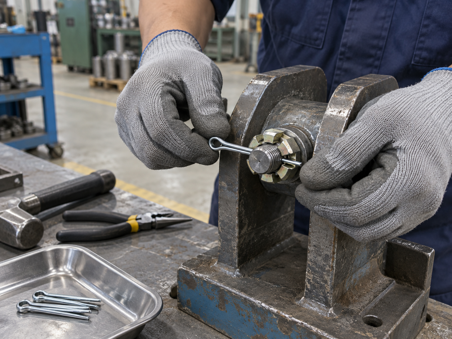
Use this general installation sequence when it agrees with the assembly drawing:
- Clean the hole and the pin. Remove chips, loose coating, and burrs that could prevent the head from seating.
- Align the bolt, clevis pin, nut slot, and mating parts without forcing the cotter pin to correct misalignment.
- Push the pin through from the accessible side. Use a soft-faced tool if light tapping is required, and protect the head from mushrooming.
- Verify that the head is seated and that both legs extend far enough beyond the joint to be bent.
- Bend the legs away from the centerline and within the available clearance. Keep the bend controlled and avoid creating a sharp kink at the eye.
- Check that the legs cannot slide back through the hole and do not interfere with motion, seals, wiring, or nearby hardware.
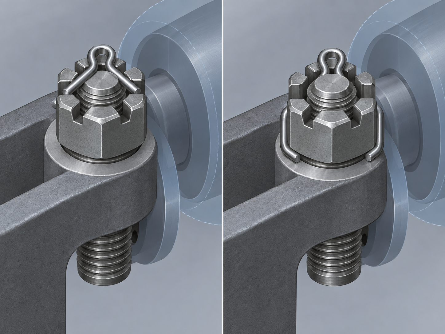
There is no single bend angle that is correct for every joint. The required bend depends on the hole, the nut or clevis geometry, the available clearance, and the maintenance instruction. A neat bend that contacts a moving component is a failure. A very short bend that can pass back through the hole is also a failure. Inspect the installed part from both sides before releasing the assembly.

To remove a cotter pin, first unload the joint if the primary fastener is under force. Straighten or cut the legs with suitable pliers or side cutters, then pull the eye or drive the pin out with a punch that fits the access path. Do not pry against a thin casting or bend a loaded clevis joint. If the pin is seized, inspect for corrosion, burrs, deformation, and a hole that has shifted out of alignment.
A bent split pin should normally be treated as a single-use retaining part. Repeated bending creates fatigue and can leave a leg cracked or permanently weak. Replace the pin after service unless the governing specification and maintenance procedure explicitly allow reuse for that exact retaining product.
Cotter pin vs R-clip, lock wire, and castellated nut
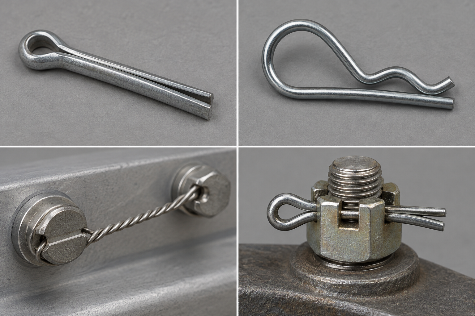
| Retaining method | Best fit | Design and service tradeoff |
|---|---|---|
| Cotter pin or split pin | A bolt, clevis pin, shaft, or castellated nut already has a transverse hole. | Visible and simple, but leg bending needs clearance and the pin is normally replaced after removal. |
| R-clip or hairpin clip | Frequent removal of a hitch pin, clevis pin, or similar part. | Fast to install and often reusable, but it needs a compatible groove, hole, and clearance envelope. |
| Lock wire | Multiple drilled fasteners need to be tied together under a controlled maintenance procedure. | Can provide visible routing, but requires drilled hardware, correct wire handling, and inspection of the installation. |
| Castellated nut plus cotter pin | A nut needs positive secondary retention on a drilled bolt or axle. | The nut and pin work as a system; torque, slot alignment, bolt hole, and pin clearance all matter. |
An R-clip is a substitute only when the mating pin and service conditions support it. A lock wire is not a quick replacement for a missing cotter pin. A castellated nut is a threaded nut with slots; it still needs a compatible bolt hole and a retaining pin when that is the specified method. If the joint has no hole or no bend clearance, ask the designer to select a different retention concept.
Material, finish, and inspection points
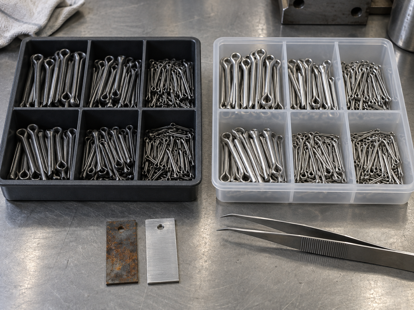
Carbon steel is common for general mechanical service. Stainless steel can be selected where corrosion exposure is important, subject to the required strength, wear, and galling review. Other alloys or special finishes may be specified for a defined environment. Availability depends on the standard, size, quantity, and supplier process, so do not assume a material grade from a product photograph.
For coated or plated pins, check whether the finish changes the effective diameter or affects the cross-hole fit. For stainless steel against a dissimilar metal, review galvanic exposure. For a joint exposed to salt, chemicals, heat, or abrasive dirt, material selection and inspection should be tied to the actual service conditions.

A practical incoming or in-process inspection can include:
- nominal diameter measured according to the selected standard;
- overall or effective length and the available leg exposure;
- eye shape, leg symmetry, end condition, and head seating;
- burrs, cracks, sharp damage, coating loss, and corrosion;
- sample fit in a controlled reference hole or the production assembly;
- material, finish, lot identification, and any certificate or inspection record required by the purchase order.
Do not assign a load rating from the pin diameter alone. The hole, bolt, nut, clevis, surrounding material, and load cycle can govern the result. A safety-critical or fatigue-sensitive design needs an engineering review and a documented acceptance method.
What to include in a cotter pin RFQ
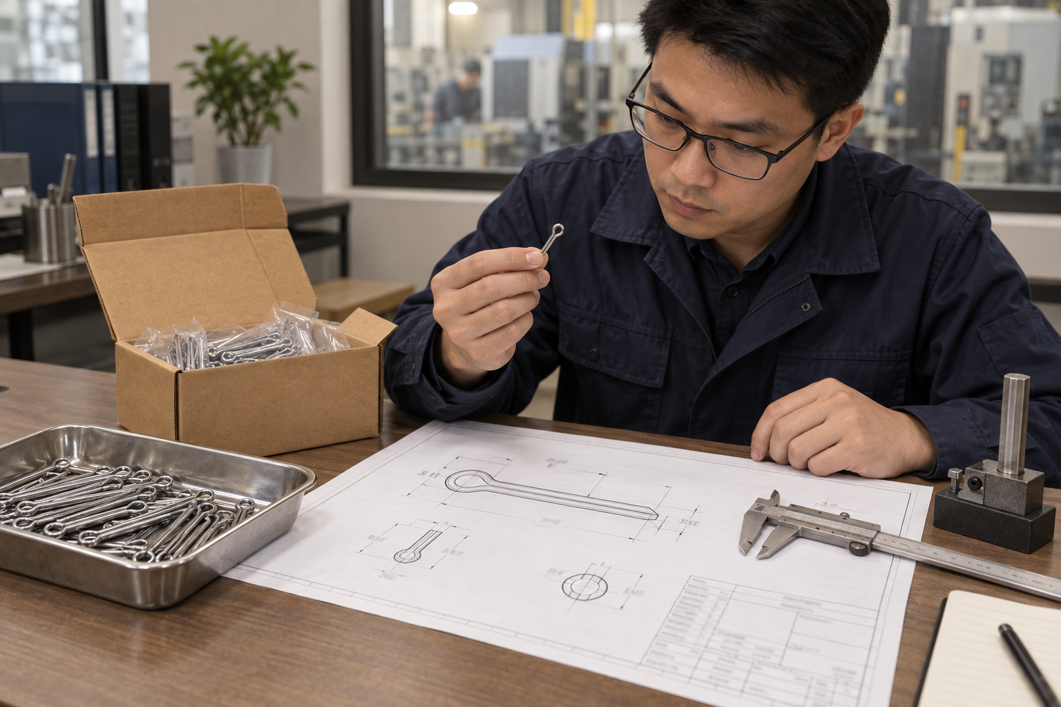
Send the supplier a part description that can be checked without guessing. Include:
- product name and application: cotter pin, split pin, castellated nut retention, clevis retention, or another defined use;
- metric or inch system and the governing standard, such as ISO 1234, DIN 94, or ASME B18.8.1 where applicable;
- nominal diameter, with the measured or controlling reference dimension identified;
- overall length, effective length, head form, leg length, and end form;
- mating bolt, clevis pin, shaft, or nut drawing, including cross-hole diameter and location;
- material grade, hardness or heat treatment if required, surface finish, and corrosion protection;
- inspection points, sample approval, documentation, and packaging requirements;
- quantity, repeat-order expectation, delivery destination, and target delivery window.
For a replacement, attach photographs of the installed part and both ends of the old pin. Record which dimensions are controlling and which are only reference measurements. If the old hole is worn or the old pin was bent incorrectly, explain that in the RFQ so the supplier can review the assembly rather than copy a damaged sample.
DingLong’s custom fastener solutions page is the right starting point for a drawing-based requirement linked to a wider screw, bolt, pin, or special fastener assembly. Send the drawing, sample, material, finish, quantity, hole details, and inspection needs for review. Final process, tolerance, MOQ, and lead time depend on the part specification.
Cotter pin FAQ
What is a cotter pin?
A cotter pin is a two-leg unthreaded retaining fastener that passes through a cross-drilled hole and is secured by bending its legs. It is also commonly called a split pin. It normally provides secondary retention for a bolt, clevis pin, shaft, or castellated nut.
Is a cotter pin the same as a split pin?
In most North American fastener catalogs, cotter pin and split pin describe the same basic two-leg product. Regional terminology can vary, so include a drawing, standard, diameter, length, and application when ordering across markets.
How do I choose a cotter pin size?
Choose the size from the actual cross-hole, the mating part, the selected standard, the effective length, and the available bend clearance. Do not select a replacement from diameter alone. Check the bolt, clevis pin, castellated nut, and hole condition as one assembly.
How do you install a cotter pin?
Align and clean the joint, insert the pin through the cross-hole, seat the eye, and bend both legs far enough to prevent withdrawal while keeping them clear of moving or sensitive parts. Follow the assembly drawing for the bend direction and any trimming requirement.
Can cotter pins be reused?
A bent split pin should normally be replaced after removal because repeated bending can fatigue or crack the legs. Reuse is acceptable only when the governing product specification and maintenance procedure explicitly permit it for the exact part and service.
What standards cover cotter pins?
Common references include ASME B18.8.1 for inch-series clevis and cotter pins, ISO 1234 for split pins, and DIN 94 for a widely used metric cotter pin reference. Confirm the current governing document, size series, and supplier dimensional table before production.
What is the difference between a cotter pin and an R-clip?
A cotter pin uses two legs that are bent after insertion and is normally a replacement part after service. An R-clip is a removable spring clip that can be reused when the mating pin has the correct hole or groove. The joint drawing and service frequency should decide between them.
What should a cotter pin supplier receive with an RFQ?
Provide the standard, unit system, nominal diameter, controlling reference end or dimension, length, head and leg form, mating hole and part drawing, material, finish, quantity, inspection needs, packaging, and delivery requirement. A sample and installed photographs help resolve an unidentified replacement.
How to specify a cotter pin without rework
A reliable cotter pin specification starts with the retaining job and the mating hole. Add the standard, diameter, effective length, leg clearance, material, finish, inspection method, and service environment. That information lets a supplier distinguish a standard split pin from a specialty retaining part and identify fit problems before production.
For a quote tied to custom screws, bolts, or other metal fasteners, use the custom fastener solutions page and send the drawing or sample with the fields listed above.